
Heating
A Careful Homeowner’s Guide to Cleaning a Furnace Flame Sensor
First confirm your manual permits access. Shut off power, clean the rod only with its approved medium, then seek diagnosis if shutdown continues afterward.
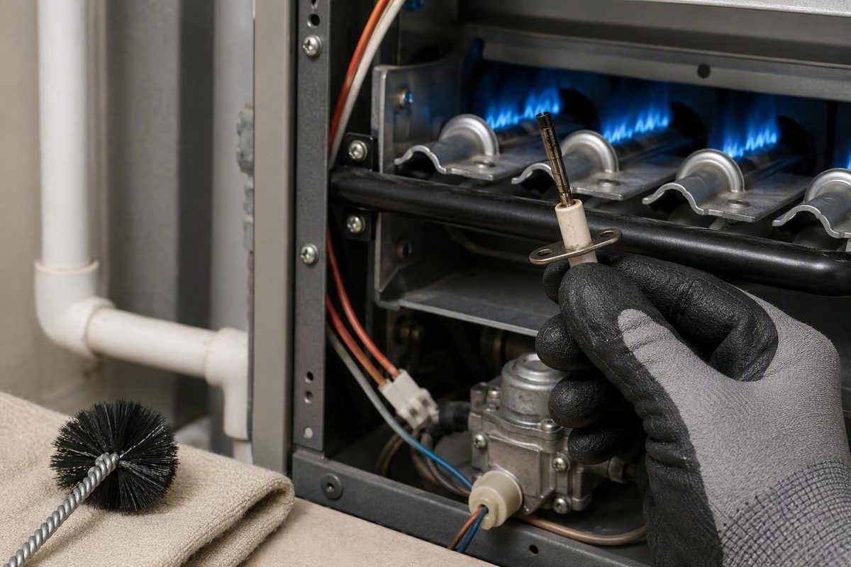
A gas furnace whose burners ignite and then shut down shortly afterward may have a contaminated flame sensor. It may instead have a sensor-position, wiring, grounding, burner, flame, venting, ignition, gas-valve, or control problem. The shutdown pattern is a clue—not a diagnosis.
This guide covers cautious cleaning of a conventional gas-furnace flame rod. It does not apply to oil furnaces, pilot assemblies, optical flame detectors, or other flame-detection systems. It also does not include live electrical measurements, combustion adjustments, gas-fitting work, burner adjustments, or control-board diagnosis.
HVAC Lens provides general homeowner information intended to improve observations and contractor conversations, not technician training or contractor advice. Equipment and installations vary, so manufacturer documentation for the exact furnace takes priority over this general procedure, consistent with HVAC Lens’s stated educational role.
Before You Begin: Know When Not to Open the Furnace
Stop and obtain qualified help if any of the following applies:
- You smell gas.
- A carbon-monoxide alarm is sounding.
- You see soot, scorching, melted insulation, or damaged wiring.
- Burner flames appear abnormal through an approved viewing point.
- Ignition is delayed, forceful, or accompanied by unusual sounds.
- The furnace repeatedly retries or enters lockout.
- You cannot identify the furnace, shutoffs, access panel, wiring, or sensor confidently.
- Access requires moving gas fittings, burners, unfamiliar wiring, or safety controls.
Gas odor, soot, scorch marks, an active carbon-monoxide alarm, and persistent malfunction are all reasons to stop homeowner troubleshooting and obtain qualified service rather than continue opening or testing the furnace under general flame-sensor guidance.
Leave the furnace alone and follow the emergency instructions supplied by your gas provider or local emergency authority. If a carbon-monoxide alarm is sounding, stop troubleshooting and follow the alarm manufacturer’s and local emergency authority’s instructions.
A flame sensor is part of the furnace’s safety system. Contractor technical guidance expressly warns that a flame sensor must not be bypassed.
Whether cleaning is an appropriate homeowner task depends on the furnace design, access arrangement, manufacturer instructions, and your ability to identify and isolate the equipment. Some conventional gas furnaces have an accessible flame rod behind a removable burner-compartment panel. Others require access or disassembly beyond the scope of this guide.
Locate the furnace model number and obtain the manufacturer documentation that applies to that exact model. Use owner-applicable operation or maintenance instructions for access and routine care. Do not undertake service-manual procedures involving live testing, gas pressure, combustion setup, safety-control testing, or technician-only diagnostics.
The applicable documentation should tell you:
- which panel may be removed;
- whether flame-sensor cleaning is an approved maintenance task;
- whether and how the model requires gas isolation;
- where the flame sensor is mounted;
- which cleaning method is permitted;
- how the panel must be reinstalled;
- how to interpret visible diagnostic indicators; and
- how utilities should be restored.
Stop if the documentation, wiring diagram, panel arrangement, or component layout does not match what you see. Also stop if a shutoff is unlabeled, inaccessible, damaged, or unfamiliar. General web instructions cannot resolve uncertainty about a specific furnace.
What the Flame Sensor Does—and What Its Symptoms Can Tell You
The flame sensor does not ignite the gas. Its purpose is to confirm that burner flame exists after ignition.
Many conventional gas furnaces use flame rectification. In plain language, the metal rod sits in the established burner flame, and the flame helps a very small electrical signal reach the control. That signal confirms combustion. If the expected signal is absent, the control stops gas flow instead of allowing the furnace to continue without proof of flame. This flame-proving process is explained in a technical overview of flame-rectification systems.
A flame-sensing problem may produce this sequence:
- The thermostat calls for heat.
- The furnace begins its startup sequence.
- The ignition source activates.
- The burners light.
- The control fails to receive adequate proof of flame.
- The control shuts down the burners.
- Depending on the model, the furnace may retry or enter lockout.
Do not assume a universal shutdown interval, retry count, reset procedure, or acceptable flame-current value. Those specifications and control behaviors vary by furnace.
Flame sensor versus igniter
The flame sensor and igniter have different jobs:
| Component | Primary job | Typical place in the sequence |
|---|---|---|
| Igniter or spark system | Starts combustion | Before or as gas reaches the burners |
| Flame sensor | Verifies that flame exists | After the burners light |
That distinction matters. If the burners ignite normally and then shut down soon afterward, the flame-proving circuit deserves attention. If the furnace never produces flame, that fact alone does not show that the sensor is dirty. The fault may occur earlier in the startup sequence.
Even normal ignition followed by rapid shutdown does not prove that contamination is the cause. A weak or missing flame signal can result from:
- a sensor installed out of position;
- a loose connector or damaged wire;
- poor grounding;
- a burner flame that does not contact the rod correctly;
- dirty or malfunctioning burners;
- weak or abnormal flame;
- ignition trouble;
- venting or combustion-air faults;
- gas-valve problems; or
- a control-board fault.
Cleaning is therefore a limited first step. It is reasonable only when the sensor is positively identified, accessible without disturbing unrelated systems, physically undamaged, and serviceable under the manufacturer’s instructions.
Find the Sensor Without Mistaking It for the Igniter
A conventional furnace flame sensor is commonly a thin metal rod extending from a ceramic or porcelain insulating base. It is mounted at or near a burner so that the rod occupies its intended position in the flame. Many designs have one lead wire and one mounting fastener, but layouts, brackets, fasteners, connectors, and rod shapes vary. A representative equipment guide describes the familiar form as a thin rod with a porcelain base near a burner.
Do not identify the sensor by location alone. A hot-surface igniter or another electrode may be mounted near the same burner assembly. Other nearby components may include rollout switches, burner crossover features, grounding connections, and ignition wiring.
Use several identifiers together:
- the exact furnace diagram;
- a component label or part number;
- the rod and insulating-base shape;
- the number and type of electrical connections;
- the mounting bracket;
- the documented position relative to the burner; and
- model-specific photographs or parts illustrations.
Before loosening anything, photograph the whole burner area. Then take closer photographs showing:
- the sensor’s mounting position;
- the rod’s angle and orientation;
- the connector seated on its terminal;
- the direction of the ceramic base;
- the wire routing; and
- the rod’s relationship to the burner.
These images are references for restoring the original arrangement. They are not a basis for changing the alignment. If the installed component appears inconsistent with the manufacturer diagram, stop rather than trying to correct it by guesswork.
Do not proceed if sensor access would require removing the burner manifold, loosening a gas fitting, moving burner parts, pulling on a wiring bundle, or working around an unidentified component. Those actions exceed the scope of flame-rod cleaning.
Tools and Cleaning Materials: Follow the Manual, Not a Universal Abrasive Rule
Gather tools only after checking the manufacturer’s instructions. You may need:
- the correctly sized screwdriver, nut driver, or socket for the actual mounting fastener;
- a clean, dry, lint-free cloth;
- the cleaning medium approved by the furnace or sensor manufacturer;
- a phone or camera for reference photographs;
- a small container for the fastener; and
- a removable wire label if several similar connections are present.
Third-party guides sometimes specify common socket or nut-driver sizes, but those sizes are not universal. Use the tool that fits the actual fastener correctly. A poorly fitting tool can damage the fastener or slip into nearby components.
Why there is no universal sandpaper answer
Published advice conflicts. Different sources recommend fine abrasive pads, emery cloth, very fine steel wool, wire brushes, fine sandpaper, paper products, or even a banknote. Other sources warn that some of these choices can scratch the rod, contaminate it, or create a surface that fouls again.
For example, one contractor guide recommends a light abrasive pad while discouraging sandpaper and bare-finger contact; other commercial procedures permit several fine abrasives. Because the evidence is inconsistent, no abrasive should be presented as universally safe. The conflicting advice is visible in this flame-sensor cleaning procedure.
Use this decision hierarchy:
- Follow the cleaning method stated by the furnace manufacturer.
- If that documentation refers to separate sensor instructions, follow the specified sensor manufacturer’s method.
- If no approved method can be found, do not assume that sandpaper, emery cloth, steel wool, a wire brush, or an abrasive pad is safe for the part.
- Ask the manufacturer, an authorized parts supplier, or a qualified HVAC technician.
- If the rod is damaged or the proper method remains uncertain, stop rather than experiment.
The objective is to remove accessible surface buildup or oxidation while removing as little underlying metal as possible. The rod does not need a mirror finish.
Regardless of the approved cleaning medium, avoid:
- files;
- rotary or powered tools;
- coarse abrasives;
- aggressive or repeated sanding;
- heavy pressure;
- bending or straightening the rod;
- soaking the ceramic;
- sprays, oils, polishes, or cleaners that leave a film; and
- unapproved solvents or household chemicals.
When the sensor is removed, support it by its ceramic base. Do not clamp the component or bear down on the rod. After cleaning, avoid touching the metal with bare fingers or placing it on a dirty surface.
Shut Down and Prepare the Furnace Safely
End the heating demand at the thermostat before beginning. Depending on the thermostat, that may mean selecting Off or lowering the heating setpoint below room temperature.
A thermostat setting is not electrical isolation. Before opening the cabinet, shut off furnace power at the dedicated service switch or the correct circuit breaker. If you cannot identify the proper electrical disconnect confidently, do not open the furnace. Commercial service guidance directs users to disconnect furnace power before accessing the flame sensor and also recognizes that model-specific removal procedures vary by furnace.
Allow the furnace and burner area to cool before touching internal components.
What about the gas supply?
Several commercial procedures advise isolating the gas supply before flame-sensor removal. However, valve design, location, labeling, access, and restoration procedures vary. There is no universal gas-valve sequence appropriate for every furnace and installation.
Follow the exact furnace manufacturer’s instructions. If the applicable documentation requires gas isolation, complete that procedure before continuing. If the valve is unfamiliar or the shutdown and restoration sequence is unclear, use a qualified technician.
Do not loosen, disconnect, test, or reposition a gas fitting as part of this task. If restoring service would require a relighting or startup procedure you do not understand, stop.
Prepare the work area before opening the cabinet:
- provide stable lighting;
- keep the correct tool and cleaning cloth within reach;
- place removed fasteners in a container;
- keep tools off burners, wiring, and cabinet edges;
- avoid pulling on wire bundles;
- do not move gas piping, the burner manifold, or burner components;
- do not alter switches, pressure tubing, grounds, or cabinet safety devices; and
- keep other people and pets away from the open furnace.
Remove only the access panel identified by the applicable documentation. If another panel, structural member, burner component, or gas part blocks access, stop rather than dismantling more of the furnace.
How to Remove and Clean the Flame Sensor
These steps assume that the exact furnace documentation permits homeowner access and cleaning, the flame sensor has been positively identified, and no stop-work condition is present.
1. Verify isolation and temperature
Before touching an internal component, confirm that:
- electrical power has been isolated;
- the furnace and burner area have cooled; and
- any gas-isolation procedure required by the manufacturer has been completed.
If any condition is uncertain, do not proceed.
2. Remove the approved access panel
Follow the manufacturer’s instructions for releasing or removing the burner-compartment panel. Support the panel as it comes free, then place it where it cannot fall, bend, or be damaged.
Note how its tabs, screws, and edges engage with the cabinet. Do not tape, clamp, hold, or otherwise defeat that device later.
3. Identify the component a second time
Compare the component with the manual, parts diagram, and your earlier photographs. Verify:
- the metal sensing rod;
- the ceramic or porcelain insulating base;
- the lead wire and connector;
- the mounting bracket and fastener;
- the original rod orientation; and
- the documented position relative to the burner.
Stop if you may be looking at the igniter or another electrode.
4. Photograph and label the connection
Take close photographs before disconnecting the lead. Include the terminal, connector orientation, bracket, wire route, and nearby fixed landmarks.
If several similar wires are present, place a removable label on the wire insulation. Do not put ink, adhesive, oil, or tape on the rod or ceramic. If the connector arrangement differs from the documentation, stop.
5. Disconnect and remove the sensor carefully
If it does not release with appropriate gentle force, consult the manufacturer’s instructions instead of twisting or prying against the ceramic.
Use the correctly fitting hand tool to remove the mounting fastener. Support the ceramic base so the sensor does not drop or rotate as the fastener comes free. Store the fastener safely.
Slide the sensor out along the path allowed by its bracket and opening. Do not bend the rod to clear a burner, wire, or cabinet edge. If removal requires flexing the sensor, shifting another component, or applying significant force, stop.
6. Inspect before cleaning
Under good lighting, examine the rod, ceramic base, bracket, terminal, connector, and visible wire insulation.
Do not clean and reinstall the sensor as though it were serviceable if you find:
- cracked, chipped, or loose ceramic;
- a bent or deformed rod;
- deep pitting;
- heavy corrosion;
- a damaged terminal;
- burned, brittle, cut, or melted insulation;
- a loose or damaged connector; or
- damage that makes the original alignment uncertain.
Do not straighten the rod, glue the ceramic, rebuild a terminal, or sand away deep damage. Commercial equipment guidance distinguishes removable surface fouling from cracked porcelain, pitting, bending, and heavy corrosion that call for replacement or professional evaluation.
Not every color change proves failure. A general article cannot reliably distinguish harmless discoloration from damaging corrosion on every sensor. If the appearance is ambiguous, compare it with manufacturer criteria or have the part inspected.
7. Clean only with the approved method
Hold the component by its ceramic base. Using only the cleaning medium approved for the furnace or sensor, apply light, controlled strokes to the accessible metal rod.
Work gradually. The purpose is to lift removable surface buildup—not to reshape the rod, remove substantial metal, or erase every discoloration. Do not scrub the ceramic, terminal, bracket, or wire unless the manufacturer specifically instructs you to do so.
If gentle cleaning does not remove the buildup, do not escalate to a file, coarse abrasive, powered brush, aggressive sanding, heavy force, or improvised chemical. Resistant deposits call for evaluation or replacement, not increasingly aggressive cleaning.
8. Remove loosened residue
Wipe the metal rod with a clean, dry, lint-free cloth. Use light pressure and make sure no fibers, grit, or loosened material remain on the rod or ceramic.
Do not apply oil, polish, lubricant, contact cleaner, household spray, or another film-forming product. Do not blow loosened debris toward the burners or other furnace components.
9. Protect the cleaned surface
Handle the sensor by its ceramic base from this point onward. Avoid touching the cleaned rod with bare fingers. If it cannot be reinstalled immediately, place it on a clean, dry surface where it will not roll or be struck.
Stop once accessible surface buildup has been addressed without visible damage or substantial metal removal. A mirror finish is neither required nor the goal.
This homeowner procedure ends with inspection, gentle cleaning, reinstallation, and one cautious operational check. It does not include live flame-current measurement, burner adjustment, gas-pressure work, gas-fitting work, control-board probing, combustion analysis, or safety-device bypassing.
Reinstall the Sensor and Check One Heating Cycle
Reassembly is not an opportunity to improve or guess at sensor alignment. The rod must return to the documented position intended by the furnace design.
Reinstall in the original orientation
Compare the sensor with your pre-removal photographs and the furnace diagram. Guide it through the original opening without striking the rod against the burner or cabinet. Seat the bracket flat at its mounting point.
If the sensor no longer fits naturally, remove it and reassess. Do not force the bracket or bend the rod. Do not select a different angle based on where you think the flame should be.
Start the mounting fastener by hand where practical to reduce the risk of cross-threading. Tighten it only until the bracket is secure and snug. Excessive tightening can damage the ceramic, bracket, threads, or mounting point.
Reconnect the lead firmly by the connector body. Compare the wire route with your photograph and confirm that it:
- follows the original path;
- is not stretched;
- is not pinched by the bracket or panel;
- does not contact an inappropriate hot surface; and
- does not interfere with another component.
Do not reroute, splice, or repair the wire as part of sensor cleaning.
Close the cabinet before operating
Replace and secure the access panel exactly as directed. Confirm that its tabs, screws, and edges are properly seated.
Otherwise, use permitted indicators such as startup sounds, a status display visible with the cabinet closed, and the normal delivery of heated air.
If gas was isolated, restore it only under the model-specific manufacturer instructions. Then restore electrical power.
Conduct one cautious heating check
Call for heat at the thermostat and observe only from a safe, permitted position. A promising result is that:
- the furnace begins its normal startup sequence;
- ignition occurs without unusual delay or force;
- the burners do not repeat the original immediate shutdown; and
- heating continues normally while there is demand.
Do not use an arbitrary burner runtime as the standard. Cycle duration can vary with thermostat demand, staging, control logic, furnace capacity, and indoor conditions. The meaningful comparison is whether the original rapid shutdown has stopped.
Stop troubleshooting and follow the gas-emergency instructions supplied by your gas provider or local authority.
For non-gas warning signs—such as unusual ignition, abnormal burner appearance through an approved port, soot, scorching, repeated retries, another rapid shutdown, a new error indication, or unusual electrical or mechanical sounds—end the heating demand if it can be done without approaching an unsafe condition, then obtain qualified service.
Do not keep resetting the furnace in an effort to make it run. Record what happened and consult the model documentation or a qualified technician.
If Cleaning Does Not Work: Clean, Replace, or Call?
Use one careful cleaning as a decision point, not the beginning of repeated abrasion.
| Condition | Appropriate path |
|---|---|
| Removable surface buildup, no physical damage, positive identification, and manufacturer-approved access and cleaning | Clean once and conduct one cautious heating check |
| Cracked ceramic; bent, deformed, deeply pitted, or heavily corroded rod; damaged terminal, connector, or wire | Obtain the correct replacement or professional evaluation |
| Furnace still shuts down after one careful cleaning | Stop cleaning and arrange diagnosis |
| Fouling returns quickly | Investigate the burner, flame, grounding, or combustion-air condition |
| Gas odor, alarm, soot, scorching, abnormal flame, unusual ignition, unfamiliar wiring, or repeated lockout | Stop immediately and obtain qualified help |
If the shutdown continues
Before removing power, record any error code or status-light pattern that is safely visible with the cabinet closed. Do not remove a panel or bypass an interlock merely to read a code.
Then isolate power before making these limited visual checks:
- Did the sensor return to its documented original position?
- Is the mounting bracket fully seated?
- Is the connector firmly attached?
- Does the wire follow its original route?
- Is there visible damage to the connector or insulation?
- Is the access panel correctly installed?
Do not probe terminals, alter grounding, move burners, or remove additional components.
Persistent shutdown may involve poor grounding, a damaged wire, burner contamination, weak or abnormal flame, ignition trouble, venting faults, the gas valve, another safety circuit, or the control board. Because these possibilities can require live electrical and combustion testing, continued failure is a diagnosis problem—not a reason to polish the rod again.
Live DC-microamp flame-signal testing is technician-level work. It requires measurement while electrical and combustion equipment is operating, interpretation against the exact manufacturer specification, and an understanding of grounding and burner behavior. General ranges published online should not replace model-specific requirements.
When replacement is appropriate
Do not try to restore a damaged sensor by straightening, grinding, gluing, or aggressive polishing. Replacement or professional evaluation is appropriate when the ceramic is cracked, the rod is bent or deeply pitted, corrosion is heavy, the terminal is damaged, or model-specific diagnosis establishes that the sensor has failed.
A replacement must match the furnace model and specified part number or approved substitute. Visual resemblance is not enough. Rod length, bends, bracket geometry, ceramic dimensions, terminal design, and intended flame position can differ.
If compatibility cannot be verified through furnace documentation or an authorized parts source, have a qualified technician select and install the part.
Treat recurring fouling as evidence
If the rod becomes contaminated again quickly, do not establish a cycle of repeated removal and abrasion. Recurring fouling can indicate an unresolved burner condition, poor grounding, abnormal flame contact, or combustion-air contamination. Technical guidance on recurring flame-rod trouble recommends examining burner condition, grounding, flame quality, and combustion-air contaminants.
Those conditions require diagnosis rather than another cleaning.
Prepare a useful service record
Before contacting a contractor, record:
- the furnace manufacturer and full model number;
- the thermostat behavior;
- any exact error code or status-light pattern;
- whether the igniter activated;
- whether the burners lit;
- how soon shutdown occurred;
- whether the furnace retried;
- unusual sounds, odors, soot, or visible damage;
- whether cleaning changed the sequence;
- the cleaning method used; and
- whether the sensor, connector, or wire appeared damaged.
Do not repeatedly reset the furnace to collect more observations. Lockout and reset behavior must be interpreted through the exact model documentation.
Follow the furnace manufacturer’s maintenance schedule rather than adopting a blanket annual flame-sensor cleaning rule. Sensor inspection can be included in appropriate furnace service, with cleaning performed when the manufacturer’s instructions and the component’s condition justify it.
Frequently Asked Questions
Can I clean a furnace flame sensor without removing it?
Only if the manufacturer’s instructions for the exact furnace permit in-place cleaning.
In-place access and removal each create model-specific risks. Cleaning in place may limit inspection and put tools close to the igniter or burner. Removal may require handling a fragile component and connector. Neither method should be treated as universally preferable.
When manufacturer-authorized removal provides access, it may allow inspection of the rod, ceramic, bracket, terminal, connector, and visible wire. If either method requires awkward force, bending, or disturbance of nearby components, stop.
Can I use sandpaper, steel wool, or emery cloth on a flame sensor?
There is no universal answer. Published sources conflict about fine sandpaper, emery cloth, steel wool, wire brushes, abrasive pads, and paper products. Some permit particular fine abrasives, while others warn that they may scratch or contaminate the rod.
Use only the method specified by the furnace or sensor manufacturer. If no approved method is available, do not assume that a commonly recommended abrasive is safe. Ask the manufacturer, an authorized parts supplier, or a qualified technician.
Whatever method is approved, use light pressure. Avoid files, coarse abrasives, powered tools, aggressive sanding, bending, and chemicals that leave a film.
Why does my furnace ignite and then shut off after a few seconds?
The control may not be receiving the expected proof-of-flame signal, causing it to stop gas flow. Surface buildup on the sensor can produce that pattern, but it is not the only possible cause.
Other possibilities include sensor misalignment, a loose connection, damaged wiring, poor grounding, dirty burners, abnormal flame, ignition trouble, venting faults, a gas-valve issue, or a control fault. A furnace that never ignites may have a problem earlier in the startup sequence rather than a dirty flame sensor.
Use the exact error code and sequence of operation as evidence. If one careful, manufacturer-approved cleaning does not correct the shutdown, arrange diagnosis instead of repeatedly cleaning or resetting the furnace.
How often should a furnace flame sensor be cleaned?
Follow the furnace manufacturer’s maintenance schedule. The supplied evidence does not establish a universal interval appropriate for every furnace, installation, fuel condition, and household environment.
Some commercial articles recommend annual cleaning, but that does not make annual abrasion necessary for every model. A better approach is to include sensor inspection in appropriate furnace service and clean it when the manufacturer directs or when its condition and the operating symptoms support doing so.
Rapid recurring fouling should be treated as a diagnostic clue, not a reason for increasingly frequent cleaning.
When should a flame sensor be replaced instead of cleaned?
Seek the correct replacement or professional evaluation when:
- the ceramic or porcelain is cracked, chipped, or loose;
- the rod is bent or deformed;
- the metal is deeply pitted;
- corrosion is heavy;
- the terminal is damaged;
- the connector or wire has heat or physical damage;
- the sensor cannot be returned confidently to its original position; or
- model-specific diagnosis establishes that the sensor has failed.
If the furnace still shuts down after one careful cleaning, do not replace the sensor solely because it looks suspicious. Other faults can produce the same behavior. A qualified technician can evaluate flame quality, grounding, wiring, burner operation, venting, the gas valve, and the control system.
The practical rule is straightforward: identify the component from the exact furnace documentation, isolate the equipment as the manufacturer directs, use only an approved gentle cleaning method, reinstall the sensor in its original position, and conduct one cautious heating check. If the sensor is damaged, shutdown continues, fouling returns quickly, or a gas, combustion, electrical, or safety warning appears, stop troubleshooting and give a qualified HVAC technician the model number, error code, observed ignition sequence, and work already performed.