
Cooling
Why Indoor Airflow Stops—and What to Check Before You Call
One marketplace estimate puts blower-motor replacement at $300–$900. Testing separates motor failure from control faults, wheel damage or airflow restrictions.
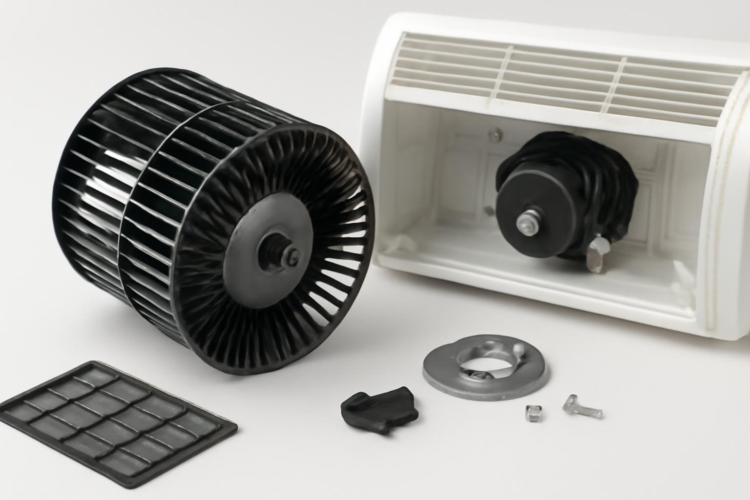
When an air conditioner is running but little or no air reaches the rooms, the indoor blower is an obvious suspect—but it is not the only one. A clogged filter, frozen evaporator coil, blocked return, damaged blower wheel, lost control signal, electrical fault, or incorrect fan setting can produce similar symptoms.
The useful question is not simply, “Is the blower motor bad?” It is, “What is preventing the indoor system from moving the required air?”
This guide explains how to identify the correct fan, sort symptoms, complete safe external checks, recognize conditions that warrant shutdown, and prepare for professional diagnosis. It covers residential ducted central air conditioners, heat pumps with air handlers, and furnace-based systems. It does not instruct homeowners to open equipment, test live voltage, handle capacitors, alter wiring, or work on refrigerant components.
First, identify which fan and system the search refers to
In residential HVAC, the air conditioner blower fan is the indoor assembly that moves air through the indoor cooling or heating section and into the home’s ductwork. The blower pushes air over an evaporator for cooling and then through the ductwork into the living space Here’s the Difference Between Blowers and Fans | Angi. During heating, the same blower may move air across a furnace heat exchanger, electric heating elements, or an indoor heat-pump coil.
That is why the part may be described as an AC blower, furnace blower, furnace fan, air-handler fan, or indoor fan. The name changes with the equipment and season, but the central function is air circulation. The blower is generally housed in an air handler when the home uses electric heat or a heat pump, or in a furnace when the furnace serves as the indoor air-moving unit.
The outdoor condenser fan performs a different job. It moves outdoor air across the condenser coil so the system can reject heat collected indoors. It usually has visible propeller-style blades beneath or behind a grille. The indoor blower wheel is normally enclosed within the furnace or air handler. This distinction between the indoor blower and outdoor fan is summarized in this residential blower overview.
The outdoor unit may continue operating while the indoor blower stops or the indoor airflow path becomes blocked. Hearing the outdoor unit while no air comes from the vents therefore narrows the concern toward the indoor equipment, controls, or airflow path. It does not prove that the blower motor failed.
For example, the motor could be operational while ice blocks the evaporator coil. The motor might not be receiving a command from the thermostat or control board. A relay could fail, the filter could be severely restricted, or the blower wheel could be loose or damaged. Treat outdoor-unit operation as a location clue, not a parts diagnosis.
This guide concerns residential ducted HVAC:
- Residential central AC and heat pumps: Usually use an indoor direct-drive blower in a furnace or air handler.
- Commercial equipment: May use larger direct-drive or belt-driven blowers, different controls, and different service procedures.
- Automotive AC and heater blowers: Use vehicle-specific parts and fitment rules. They are not comparable to residential HVAC components even when catalog terminology looks similar.
- Ductless mini-splits and window units: Use different fan arrangements and require equipment-specific troubleshooting.
A typical residential airflow path starts at a return grille, continues through the return duct and filter, crosses the indoor conditioning section, passes through the blower and supply plenum in the equipment-specific order, and ends at the room registers. The outdoor condenser and its fan form a separate airflow circuit outside the home.
Correctly identifying the fan prevents a common purchasing error: comparing an indoor blower motor with an outdoor condenser-fan motor—or with an automotive blower that happens to look similar.
Know the parts before calling the whole assembly a motor
“Blower fan” is often used as shorthand for several connected parts. An estimate or retail listing may refer to only one of them, so clarify what is actually being tested, repaired, or sold.
The main components are:
- Blower wheel: The rotating enclosed impeller—often called a squirrel-cage wheel—that physically moves air.
- Blower motor: The electrical component that turns the wheel.
- Shaft: Connects the motor to the wheel in a typical direct-drive assembly.
- Housing: Encloses the wheel and shapes the airflow.
- Mounts or brackets: Secure the motor and assembly while limiting unwanted movement.
- Relay or control board: Sends or switches the command that starts, stops, or changes blower operation.
- Run capacitor: Supports operation on applicable permanent split capacitor, or PSC, motor designs.
- Electronic module: Controls applicable electronically commutated motors, or ECMs.
- Complete blower assembly: May include the motor, wheel, housing, mounts, electronics, or some combination of those components.
A motor-only listing does not necessarily include the wheel, housing, mounting hardware, capacitor, or electronic controls. Likewise, a quote for a “blower assembly” may cover considerably more than the motor. Ask for an itemized description rather than relying on the word blower.
Motor and control arrangements also differ:
- Single-speed: Operates at one configured speed when called.
- Multi-speed: Provides preset speed selections used for different operating modes.
- Constant-torque: Uses electronic control to respond according to its design and configured inputs.
- Variable-speed: Can adjust operation across a broader range in response to system commands.
These are control arrangements, not interchangeable marketing tiers. A variable-speed motor cannot be substituted merely because it sounds more advanced, and a single-speed replacement is not automatically suitable for equipment designed around electronic airflow control. Manufacturer guidance distinguishes single-speed, multi-speed, and variable-speed blower designs, but actual compatibility remains equipment-specific.
The distinction between PSC and ECM equipment is especially important during troubleshooting. Many PSC designs use a separate run capacitor. A technician may test that capacitor when the motor hums, starts poorly, overheats, or fails to run. An ECM instead uses matched electronics and follows a different diagnostic path; it should not automatically be evaluated using PSC capacitor assumptions. Some ECM failures involve the electronic module rather than the motor section.
Most residential systems covered here use a direct-drive arrangement, meaning the motor shaft drives the blower wheel directly. Some older equipment and larger systems use belts. A belt, pulley, or belt-tension problem adds another mechanical failure path, but a belt-driven commercial blower should not be treated as equivalent to a typical residential air-handler blower.
Physically, a blower assembly can be understood as a motor mounted to a housing, with its shaft connected to the enclosed wheel. Depending on the design, a PSC capacitor or ECM module supports motor operation, while the evaporator coil sits upstream or downstream according to the equipment layout.
Understanding the individual parts leads to a better service question. Instead of asking, “How much is a blower?” ask whether the diagnosis concerns the motor, wheel, capacitor, electronic module, relay, control board, mounting hardware, or complete assembly.
Match the observed symptom to plausible causes—not a premature diagnosis
A symptom is a starting point. It can organize likely categories, but it cannot establish which component failed without electrical, mechanical, control, and airflow testing.
| Observation | Plausible explanations | Safe homeowner observations | Technician checks |
|---|---|---|---|
| Blower is completely silent | No thermostat demand, dead thermostat batteries, switched-off indoor unit, loss of power, wiring fault, failed relay or board, motor or module failure | Confirm cooling mode, setpoint, batteries, fan setting, accessible switch position, and whether the outdoor unit runs | Supply power, control signal, relay and board output, wiring integrity, motor or module condition |
| Humming or buzzing without airflow | PSC capacitor problem, stalled motor, mechanical obstruction, control problem, or incorrect voltage; ECM faults follow a different path | Note where the sound originates and whether an odor or breaker trip accompanies it | Motor type, capacitor condition where applicable, voltage, current, shaft and wheel mechanics, ECM fault information |
| Blower sounds as if it runs, but airflow is weak | Dirty filter, blocked return, closed registers, coil ice, duct restriction, dirty or damaged wheel, loose wheel, incorrect speed, or motor underperformance | Inspect the filter, clear grilles, check all rooms, and look for visible ice | Static pressure, airflow, filter and coil condition, duct restrictions, wheel condition, motor speed and current |
| Airflow stops and later returns | Motor overheating or thermal overload, restricted airflow, coil icing, capacitor weakness, loose wiring, intermittent relay, board, thermostat, or module fault | Record time until failure, recovery time, sounds, odors, ice, outdoor-unit behavior, and whether the fan setting changes anything | Current, temperature, capacitor where applicable, wiring under operating conditions, airflow resistance, controls, and icing causes |
| Blower works at only certain speeds | Speed connection, electronic module, thermostat, relay, board, wiring, or programming problem | Note which modes work: fan-only, cooling, heating, low stage, or high stage | Commands for each mode, speed configuration, module operation, board outputs, and programming |
| Blower never stops | Thermostat set to ON, stuck relay, control-board fault, thermostat or wiring issue, configured circulation feature | Check whether the thermostat fan setting is ON rather than AUTO | Thermostat signals, relay contacts, board logic, wiring, and configured circulation settings |
| Squealing or grinding | Bearing wear, wheel contact, shaft trouble, or another mechanical fault | Note whether the noise starts immediately or changes as the system runs | Bearings, wheel alignment, shaft, mounts, housing contact, and motor condition |
| Rattling or banging | Loose mount, damaged wheel, debris, panel vibration, broken component, or duct movement | Identify the general location without opening the unit | Wheel, housing, mounts, fasteners, debris, and nearby ductwork |
| Airflow varies substantially by room | Closed register, furniture obstruction, duct leakage or restriction, balancing problem, zoning issue, or inadequate total airflow | Open accessible registers and note affected rooms | Duct condition, dampers, zone controls, register balance, and system static pressure |
Silence
A silent blower can result from something as simple as an incorrect thermostat setting or interrupted power, but it can also indicate a failed control or motor. Confirm that the thermostat is calling for cooling, then check batteries and accessible switches.
The important professional distinction is whether the motor is not being told to run or is receiving the proper command and cannot run. Those are different failure categories and can require different repairs.
Humming without rotation
Humming is consistent with a component being energized without starting correctly, but the sound is not diagnostic. On applicable PSC equipment, a weak or failed run capacitor is one possibility. Motor damage, incorrect voltage, binding mechanics, or another electrical problem can produce similar behavior. ECM systems use a different control architecture, so “humming means capacitor” is not a dependable universal rule.
Report the sound, its duration, and whether an odor or breaker trip accompanies it. Internal motor and capacitor testing should be left to a qualified technician because it involves electrical components and, in the case of capacitors, stored energy.
Weak airflow while the blower runs
When the blower can be heard but air barely reaches the vents, begin with the airflow path rather than declaring the motor dead. Check the filter, return grilles, supply registers, and visible signs of ice. Technician-level possibilities include a dirty evaporator coil, restricted or damaged ductwork, incorrect speed configuration, or a dirty, damaged, or loose blower wheel.
A wheel can rotate without moving the intended volume of air. Dirt on its blades changes how it handles air; physical damage or looseness can reduce performance further. Hearing the motor therefore does not establish that the complete blower assembly is functioning correctly.
Intermittent shutdown and recovery
A blower that stops after operating and returns after cooling may be experiencing an overload or overheating condition. Restricted airflow is one possible contributor. Capacitor weakness on applicable equipment, wiring faults, icing, controls, and motor or module problems remain alternatives.
The timing matters. Record how long the blower operates before stopping, how long it takes to recover, whether the outdoor unit remains on, and whether visible ice or an unusual sound appears. Intermittent failures are especially likely to require testing while the fault is present.
Continuous or speed-specific operation
A blower that runs continuously may simply have the thermostat fan control set to ON. If it continues after selecting AUTO and the heating or cooling call has ended, possible causes include a stuck relay, thermostat or wiring fault, control-board problem, or configured circulation setting.
Operation at only one speed or in only one mode can point toward controls, speed connections, electronic modules, programming, or board outputs. Record whether the blower works during fan-only operation, cooling, heating, or different stages. That pattern is more informative than saying it “sometimes works.”
Noise
Squealing and grinding can be consistent with bearing or mechanical trouble. Rattling or banging can suggest loose, damaged, or contacting components. Sound alone cannot identify the failed part: vibration may travel through the housing or ducts, and noise that appears to come from the motor may originate at the wheel, mount, panel, or nearby ductwork.
The airflow-and-icing loop
Low airflow can contribute to evaporator-coil icing during cooling. As ice accumulates, it obstructs airflow further, making the initial restriction appear progressively worse. A nonoperating blower can also contribute to icing because indoor air is no longer carrying heat across the coil.
Manufacturer troubleshooting guidance treats filters, power, thermostats, controls, wiring, capacitors, motors, and frozen coils as distinct possible causes of a stopped air-handler fan—not as interchangeable proof of motor failure (Trane’s air-handler troubleshooting guide).
Use symptoms to structure the service conversation. Do not use them as substitutes for measurements.
Use a safe, noninvasive troubleshooting sequence
The purpose of homeowner troubleshooting is to rule out simple external conditions and document what the system does. It is not to reproduce an internal service diagnosis.
Work through this sequence:
-
Confirm the thermostat mode and setpoint. Select cooling mode and set the temperature below the current room temperature so there is a clear cooling demand. Allow for any normal built-in delay before deciding that nothing responded.
-
Check the thermostat fan setting. In ON, it generally operates continuously. Temporarily selecting ON can show whether the indoor blower responds independently of the cooling call. A response does not prove that every speed or control function is correct, and no response does not identify the failed component.
-
Replace thermostat batteries if applicable. If the display is blank, weak, or behaving unusually, install the specified battery type.
-
Inspect the air filter. Replace a visibly dirty or clogged filter with the correct size and an appropriate type for the equipment. Note the old filter’s condition and installation date. Do not operate the system without a filter unless equipment-specific instructions explicitly allow it.
-
Check supply registers and return grilles. Make sure accessible supply registers are open and not covered by rugs, furniture, or belongings. Keep return grilles unobstructed.
-
Inspect accessible power switches. A furnace or air handler may have a nearby switch that resembles a light switch. Confirm that an obvious, accessible switch has not been turned off accidentally.
-
Observe the breaker without repeatedly resetting it. If the HVAC breaker has tripped, leave it off and arrange inspection. Repeated resetting can re-energize an unresolved fault; manufacturer guidance likewise advises leaving a tripped air-handler breaker off until the cause has been checked (Trane).
-
Listen without opening the equipment. Record silence, humming, buzzing, clicking, squealing, grinding, rattling, or repeated attempts to start. Note whether the sound appears to come from the thermostat area, indoor equipment, ducts, or outdoor unit.
-
Look for visible warning signs. From outside the equipment, look for ice on accessible refrigerant tubing or around the indoor coil cabinet, as well as smoke, visible wiring damage, or unusual odors.
Write down:
- Whether the outdoor unit runs
- Whether air reaches any vents
- Whether some rooms have more airflow than others
- Whether the indoor blower is silent, humming, noisy, or apparently running
- Whether the failure is constant or intermittent
- How long the system runs before airflow changes
- Whether fan ON produces a different result from AUTO
- Whether visible ice, an odor, or a breaker trip is involved
Do not remove furnace or air-handler panels, touch wiring, test voltage, discharge a capacitor, spin the blower wheel by hand, alter speed settings, or work on the evaporator coil or refrigerant circuit. These actions cross into internal electrical, mechanical, and refrigerant-side work; capacitor and blower service in particular can expose a person to stored energy and moving or sharp components (United HVAC Motors’ safety discussion).
For a broader homeowner-first approach, HVAC Lens recommends checking the filter and observing system behavior before approving work. The purpose is to make a service call more productive—not to turn an external checklist into an internal repair attempt.
Know when to shut the system off
Set the HVAC system to OFF and request professional service if you notice:
- Smoke or an active burning condition
- A burning or electrical odor
- Repeated breaker trips
- Persistent electrical buzzing
- Visible wiring damage
- Signs of overheating
- Visible ice around the evaporator-coil cabinet or refrigerant line
- Severe grinding, banging, or evidence that a rotating component is contacting the housing
Do not restart the system repeatedly or keep resetting a tripped breaker. Smoke or an active burning condition warrants urgent assistance rather than continued HVAC troubleshooting. These warning signs are identified as reasons to stop operation and seek professional service in homeowner safety guidance (Quality Plumbing, Heating, Cooling and Electrical).
An odor or noise may be consistent with an electrical or mechanical fault, but it does not prove the blower motor failed. A relay, wire, control board, capacitor, electronic module, mount, wheel, or another component may be involved.
If the evaporator-coil area or accessible refrigerant line is visibly iced, set the HVAC system to OFF and arrange diagnosis. Thawing may remove the visible obstruction temporarily, but it does not identify or correct why the coil froze. Restarting the system can reproduce the condition; indoor-fan guidance specifically calls for shutting off air conditioning when the evaporator coil is frozen (Hannabery HVAC).
Capacitor work is also outside the homeowner boundary. A capacitor can retain electrical energy after equipment power is removed, so switching off the thermostat or breaker does not make capacitor terminals appropriate to touch or test. Persistent buzzing or humming should be reported rather than investigated by opening the cabinet.
Relay, control-board, wiring, motor, ECM-module, and frozen-coil problems generally require professional inspection. Equipment construction, controls, access, and shutdown procedures vary by model and installation. HVAC Lens provides general information rather than individualized contractor advice and recommends confirming major changes with a licensed professional in its information-use terms.
What a technician should test before condemning the motor
A defensible blower diagnosis should establish which component failed and whether an airflow or control condition contributed. Professional testing generally falls into five categories.
1. Power and control signals
The technician should determine whether the indoor unit has the required electrical supply and whether the blower receives the correct operating command. This can include checking:
- Incoming power
- Low-voltage control signals
- Thermostat calls
- Safety circuits
- Relay operation
- Control-board input and output
- Wiring and connections
- Commands for fan-only, cooling, heating, and staged operation
This separates two very different situations:
- The motor is not running because it is not being commanded or powered correctly.
- The motor receives the correct supply and command but fails to start, maintain speed, or operate reliably.
Replacing a motor in the first situation may leave the original control problem untouched.
2. Motor or electronic-module condition
Depending on motor type, the technician may evaluate current, starting behavior, operating temperature, bearings, shaft condition, electronic-module response, and available fault information. An ECM may require module-specific testing, communication checks, or verification that its programmed configuration matches the equipment.
There is no useful universal pass-fail number for this guide. Correct voltage, current, speed, programming, and control values depend on the equipment and motor documentation.
3. Capacitor condition where applicable
On a PSC system that uses a separate run capacitor, the technician may measure capacitance and compare the result with the component specification. The technician should also determine whether the capacitor is the isolated failure or whether motor condition, heat, wiring, or airflow contributed.
An ECM should not automatically receive the same capacitor diagnosis. The first step is identifying the motor and control architecture.
4. Blower-wheel mechanics
A functional motor cannot move air correctly if the wheel is dirty, damaged, loose on the shaft, rubbing the housing, or obstructed. Inspection may cover:
- Wheel cleanliness and blade condition
- Attachment to the shaft
- Rotation and clearance
- Bearings
- Motor mounts
- Housing damage
- Belt and pulley condition where applicable
Mechanical noise should be confirmed at its source rather than assigned to the motor from sound alone.
5. Total airflow and system resistance
A complete diagnosis should look beyond the motor to the system through which it must move air. Relevant checks can include:
- Filter condition and suitability
- Evaporator-coil cleanliness and icing
- Blower-wheel cleanliness
- Supply and return restrictions
- Duct condition
- Dampers and zoning controls
- Register balance
- Total airflow
- Static pressure or other model-appropriate resistance measurements
This broader testing matters because replacing the motor does not correct a clogged filter, dirty wheel, restricted duct, iced or dirty coil, or excessive airflow resistance. A new motor may still deliver poor airflow or operate under the same strain if the underlying condition remains.
Before approving work, ask:
- What measurement or test confirmed the failed component?
- Is the problem the motor, electronic module, capacitor, relay, wheel, control board, wiring, or airflow path?
- Was the motor receiving the correct command and power?
- What underlying condition may have contributed?
- Does the estimate correct that condition as well as the failed part?
- Was total airflow or system resistance checked?
- What model-specific specification was used to select the replacement?
A clear answer should identify evidence, not merely repeat the symptom.
Choose the correct replacement—not merely a similar-looking motor
Do not buy a replacement based only on a photograph, horsepower, voltage, or the phrase “universal motor.” Blower compatibility can depend on physical dimensions, direction of rotation, speed, mounting, controls, programming, and required airflow.
Use this replacement-information worksheet before comparing parts:
| Information to collect | Where to find or verify it |
|---|---|
| Equipment manufacturer and model number | Furnace, air-handler, or package-unit data plate |
| Equipment serial number | Equipment data plate |
| Motor manufacturer and model number | Existing motor label or service documentation |
| Motor voltage | Motor label and equipment documentation |
| Horsepower | Motor label |
| RPM or speed information | Motor label or manufacturer documentation |
| Rotation | Label, manufacturer documentation, and application requirements |
| Shaft diameter and usable length | Verified part specifications or technician measurement |
| Motor body dimensions | Verified part specifications |
| Mounting arrangement | Existing assembly and parts documentation |
| Motor control type | PSC, constant-torque ECM, variable-speed ECM, or another identified design |
| Number or arrangement of speeds | Label, wiring documentation, or programming information |
| Capacitor specification, if applicable | Specified component and equipment documentation |
| Electronic-module or programming requirements | Manufacturer or authorized-parts information |
| Required airflow or configured application | Equipment documentation and professional verification |
| Blower-wheel and housing condition | Technician inspection |
| Photographs | Full equipment data plate, motor label, connectors, mount, and assembly layout |
This worksheet organizes verification; it does not establish compatibility by itself. Labels may be incomplete, previous repairs may have changed components, and some replacement systems use cross-reference rules or programming that require manufacturer or distributor confirmation.
The correct repair may not involve a motor at all:
- An isolated failed capacitor on applicable PSC equipment may call for capacitor replacement.
- A defective relay may be replaceable without changing the motor.
- An ECM module problem may involve matched electronic components.
- A dirty, loose, or damaged wheel may require cleaning, adjustment, or replacement.
- Damage affecting the motor, wheel, housing, mounts, and electronics may justify a complete assembly quote.
Replacement categories involve different tradeoffs:
| Replacement category | Potential advantage | Main verification concern |
|---|---|---|
| OEM-specific | Clearer equipment-specific part relationship when documentation is available | Availability, superseded part numbers, programming, and included components |
| Universal | May cover several electrical or horsepower configurations | Physical fit, rotation, shaft, mounting, speed setup, controls, airflow, and installer configuration |
| Remanufactured model-specific | May provide another sourcing option for discontinued or costly electronic motors | Programming, exact model match, warranty terms, seller testing claims, connectors, and module compatibility |
| Complete assembly | Can address damage across multiple connected components | Exact equipment fit, included parts, cost, and whether complete replacement is necessary |
Some model-specific ECM replacements require correct programming for the furnace or air handler. A seller may advertise a remanufactured motor as programmed or “plug-and-play,” but that is a commercial claim tied to the listed model and seller process, not proof that it fits another system. One retailer accordingly directs shoppers to search its remanufactured motor catalog by exact motor model number.
A listing may provide voltage, horsepower, and RPM but not rotation, shaft dimensions, body dimensions, mounting arrangement, controls, connector details, or the contents of a supposed assembly. Ratings, stock labels, shipping promises, OEM-equivalence statements, and warranty headlines are seller-specific claims—not independent evidence of compatibility or reliability.
Keep automotive results out of the comparison. A car or truck blower motor may be sold with a wheel and may use familiar terminology, but its fitment, voltage, mounting, controls, pricing, and warranty do not apply to a residential furnace or air handler.
Understand cost without treating a broad range as a quote
An installed blower repair price can include much more than a motor. Break the estimate into its actual scope:
- Diagnostic or service-call fee
- Minor electrical or control component
- PSC run capacitor, where applicable
- Relay, control board, wiring, or thermostat work
- Motor
- ECM electronic module
- Programming or configuration
- Blower wheel
- Housing, mounts, or complete blower assembly
- Labor
- Difficult attic, crawlspace, closet, or rooftop access
- Filter, coil, duct, zoning, or airflow correction
- Follow-up airflow and operating verification
- Part and labor warranty
As one dated commercial example, Angi’s July 2026 marketplace guide lists $300–$900 for blower-motor replacement. That is a broad editorial estimate, not a quote for a particular motor, home, region, or repair scope (Angi’s blower-versus-fan cost guide).
A Houston contractor gives a broader $800–$2,000 category for moderate work that may include either blower-motor or evaporator-coil replacement. That category is not directly comparable with Angi’s motor estimate because it combines different repairs and reflects a particular regional service market (Houston repair-versus-replacement guidance).
Several factors can move the total:
- Motor technology and control type
- OEM-specific or model-specific part requirements
- ECM module programming
- Limited part availability
- Difficult equipment access
- Wheel, housing, mount, relay, board, or wiring damage
- Coil cleaning or icing diagnosis
- Duct or airflow restrictions
- Local labor and service conditions
- After-hours or urgent scheduling
Do not compare a retail motor price directly with an installed service estimate. The retail listing may omit the module, programming, wheel, mounts, diagnostics, labor, warranty administration, and correction of the condition that caused the complaint. Conversely, a high installed quote should identify those added items rather than using “blower motor” as an all-purpose explanation.
Keep three decisions separate:
-
Repair an isolated component. Appropriate when testing identifies a capacitor, relay, connector, wheel, or other limited fault and the remaining components are serviceable.
-
Replace the motor, module, or complete blower assembly. Appropriate when testing confirms that component has failed or when damage and parts availability make assembly replacement more practical.
-
Replace the entire HVAC system. A broader decision involving overall equipment condition, repair history, comfort performance, available parts, efficiency goals, and other existing problems.
System age can inform the conversation, but it is not an automatic verdict. Neither is a repair-to-replacement percentage. An older system with an isolated, verifiable blower fault presents a different decision from one with repeated failures, major coil or refrigerant problems, poor comfort, and obsolete controls.
Ask these estimate questions:
- What exact part numbers are included?
- Is this motor-only, motor plus module, or a complete assembly?
- Is required ECM programming included?
- Does the price include diagnosis and labor?
- What part and labor warranty applies?
- Is blower-wheel or coil cleaning included?
- Will airflow or static pressure be checked after the repair?
- Does the estimate correct an underlying restriction or control problem?
- Why is full-system replacement being proposed for an isolated blower complaint?
- What additional defect makes replacement preferable to the documented repair?
The best estimate is not necessarily the lowest or highest. It is the one that clearly connects measurements, failed components, compatibility, labor, and corrective work.
Reduce repeat strain and prepare a better contractor handoff
A blower must move air through the filter, coil, ducts, dampers, and registers. Restriction anywhere along that path can reduce vent airflow and add strain. It can also contribute to overheating or evaporator-coil icing, although a dirty filter does not automatically mean the motor has suffered permanent damage.
Inspect filters according to actual conditions rather than relying on one universal calendar. Relevant factors include:
- Filter type, size, depth, and condition
- Equipment instructions
- System runtime
- Number of occupants
- Pets
- Indoor and outdoor dust
- Smoke or cooking particles
- Renovation or construction activity
- Seasonal pollen
- Existing airflow sensitivity
A filter that remains relatively clean under light use may not need the same schedule as one serving a home with pets, heavy runtime, smoke, or renovation dust. Check it regularly enough to learn how quickly conditions change in your home, then adjust according to equipment and filter guidance.
Keep accessible supply registers open unless a qualified professional has designed another balancing strategy. Keep return grilles clear of furniture, curtains, boxes, and household items. Internal blower-wheel, coil, electrical, and motor work should be left to qualified service.
Periodic professional maintenance should evaluate the blower in context rather than inspecting the motor alone. Depending on the system, that may include the wheel, mounts, controls, electrical connections, filter, evaporator coil, condensate management, operating commands, and total airflow.
Before the technician arrives, prepare this handoff:
- Equipment manufacturer and model number
- Motor model number, if available from prior records or existing photographs
- Filter size, condition, and last replacement date
- Thermostat mode and setpoint used during testing
- Result with the fan set temporarily to ON
- Whether airflow reaches any vents
- Which rooms are most affected
- Whether the outdoor unit continues running
- Visible ice and its location
- Humming, buzzing, clicking, grinding, squealing, rattling, or banging
- Burning, electrical, musty, or other unusual odors
- Breaker-trip history
- How long the system operates before failure
- Whether operation returns after the system cools
- Previous blower, capacitor, module, control-board, or duct repairs
- Photos of data plates and visible external conditions
This record helps the technician reproduce the complaint, especially when operation is intermittent. It also makes it easier to compare the eventual diagnosis with the symptoms rather than approving a replacement based on an assumption.
As explained in HVAC Lens’s homeowner-focused editorial approach, the goal is to make maintenance calls and estimates easier to understand—not to turn readers into technicians. Read the system before approving work, but do not cross into internal electrical, mechanical, or refrigerant-side troubleshooting.
The best outcome is not merely obtaining a new motor. It is confirming which component failed, matching any replacement correctly, and correcting the airflow or control condition that may have contributed.
Air Conditioner Blower Fan FAQs
Should the air conditioner blower fan be set to ON or AUTO?
For ordinary cooling operation, AUTO is generally the normal choice: the blower responds to heating or cooling calls rather than running continuously. ON tells the fan to operate continuously or according to the system’s continuous-fan configuration.
Temporarily selecting ON is useful as an observation. If the blower responds in ON but not during a cooling call, that pattern may help a technician focus on thermostat, control, staging, or command issues. If it does not respond, possible causes still include power, controls, wiring, a motor, or an electronic module. The test does not identify the failed component.
Some thermostats also provide circulation or scheduled-fan modes. Check the thermostat and equipment documentation before interpreting continuous operation as a fault.
Why is the outdoor AC unit running when no air comes from the vents?
The indoor blower and outdoor condenser fan are separate components with different controls and functions. The outdoor equipment can continue operating even if the indoor blower loses power, fails to receive a command, overheats, or experiences a motor, capacitor, module, relay, or wiring fault.
No vent airflow can also occur when the blower runs but the airflow path is severely restricted by a clogged filter, blocked return, frozen evaporator coil, dirty or damaged wheel, or duct problem.
Set the HVAC system to OFF if visible ice, electrical odors, smoke, repeated breaker trips, or persistent buzzing are present. Otherwise, document the thermostat settings, fan-ON test, sounds, filter condition, outdoor-unit behavior, and whether any vents receive air.
Can a dirty filter stop or damage an air conditioner blower fan?
A dirty filter can restrict airflow, reduce delivery at the vents, increase blower strain, and contribute to overheating or evaporator-coil icing. In some situations, an overheating motor may stop and later recover after cooling.
That does not mean every dirty filter permanently damages a blower motor or that replacing the filter proves the rest of the system is healthy. Coil condition, duct restrictions, wheel cleanliness, motor controls, and overall system resistance may also matter.
Replace a visibly dirty filter with the correct size and an appropriate type. If airflow remains weak, the blower stops again, or ice appears, set the system to OFF and arrange professional diagnosis rather than continuing to restart it.
How much does air conditioner blower motor replacement cost?
One July 2026 home-services marketplace guide lists $300–$900 for blower-motor replacement. A Houston contractor lists $800–$2,000 for a wider category of moderate repairs that can include blower-motor or evaporator-coil work (Champion & Nash). The figures use different scopes and markets and should not be treated as competing universal quotes.
The final price depends on the motor and control type, electronic module, programming, part availability, equipment access, labor, wheel or assembly damage, and any airflow, coil, duct, relay, wiring, or control work. Ask whether the estimate includes diagnosis, exact parts, programming, labor, airflow verification, and both part and labor warranties.
Can a homeowner replace an air conditioner blower motor?
Blower-motor replacement generally exceeds the safe scope of a homeowner guide. The work can involve internal wiring, stored capacitor energy, sharp cabinet surfaces, a rotating wheel, motor mounting and alignment, speed configuration, ECM programming, and verification that airflow is correct afterward. Capacitors may retain electrical energy even after the equipment has been switched off, and internal blower work should not be attempted without appropriate training and procedures (United HVAC Motors’ electrical-safety guidance).
A replacement that looks similar may still have the wrong rotation, shaft, mounting, controls, dimensions, or airflow characteristics. Misdiagnosis can also result in replacing a functioning motor while leaving a control, wheel, coil, duct, or electrical problem unresolved.
Homeowners can contribute by checking external thermostat settings, batteries, filters, registers, return grilles, accessible switches, visible ice, sounds, odors, and breaker history. Leave panel removal, electrical testing, capacitor work, internal mechanical work, motor replacement, programming, and refrigerant-side diagnosis to a qualified professional.