
Cooling
What an AC Subcooling Reading Means—and How the Math Works
Convert liquid-line pressure to the correct refrigerant's saturation temperature, then subtract actual line temperature. The target is model-specific.
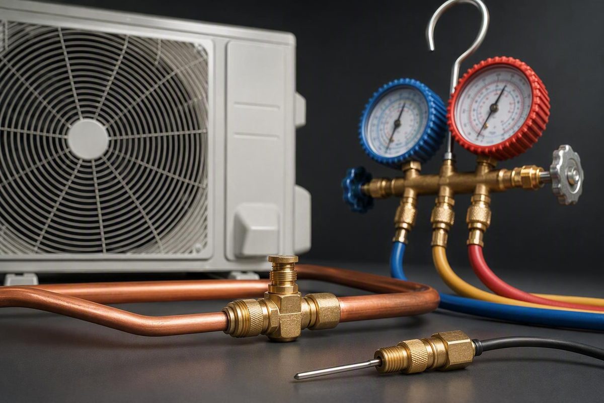
The subcooling formula and the short answer
Subcooling = condensing saturation temperature at measured liquid-line pressure − actual liquid-line temperature
Subcooling is the number of degrees that liquid refrigerant is below its saturation, or condensing, temperature at the pressure being measured. The calculation compares:
- the temperature at which the installed refrigerant would be saturated at the measured liquid-line pressure; and
- the actual surface temperature of the liquid line near that pressure measurement.
The formula is commonly written as:
Subcooling = saturation temperature − liquid-line temperature
The first number is not the outdoor-air temperature. It is also not the temperature of the hot discharge line between the compressor and condenser. It is a saturation temperature derived from the system’s high-side liquid-line pressure using pressure-temperature data for the installed refrigerant.
The liquid-line temperature is measured between the condenser and metering device, normally near the condenser outlet or liquid service valve. The pressure and temperature must come from the liquid side rather than the compressor discharge line.
A technician therefore needs three basic inputs:
- Refrigerant type, identified from the equipment data plate or applicable service documentation
- Liquid-line or high-side pressure
- Actual liquid-line temperature
The result is expressed as a temperature difference. For example:
84°F saturation temperature − 74°F liquid-line temperature
= 10°F of subcooling
That supported example is shown in ETI’s subcooling measurement procedure.
“10°F of subcooling” does not mean the refrigerant is at 10°F. It means the measured liquid line is 10 degrees below the refrigerant’s saturation temperature at the corresponding pressure.
This distinction matters when reviewing a service report. A report that lists only “subcooling: 10°F” gives the result but not enough information to audit it. A complete record should identify:
- the installed refrigerant;
- measured high-side pressure;
- saturation temperature derived from that pressure;
- measured liquid-line temperature;
- pressure and probe locations;
- operating mode and stage; and
- model-specific target or charging chart.
Most importantly, calculation and diagnosis are separate steps. The subtraction produces a reading. By itself, that reading does not establish that the refrigerant charge is correct or prove that the system is undercharged, overcharged or otherwise healthy.
Why pressure must be converted to saturation temperature
Refrigerant pressure and saturation temperature are related. At a given pressure, a particular refrigerant has a corresponding temperature at which liquid and vapor can coexist. That is the refrigerant’s saturation temperature at that pressure.
The relationship is refrigerant-specific. The same pressure can correspond to different saturation temperatures for different refrigerants. Consequently, entering a correct pressure under the wrong refrigerant selection produces the wrong saturation temperature and invalidates the resulting subcooling calculation.
A technician can perform the pressure-to-temperature conversion using any of four common methods:
- a refrigerant-specific pressure-temperature, or P/T, chart;
- the correct refrigerant scale on a compatible analog gauge;
- a refrigerant P/T app; or
- a digital manifold set to the correct refrigerant.
The equipment data plate, installation literature or service records should identify the refrigerant. The chart, gauge scale, app or digital-manifold setting must match it. A calculator may perform perfect arithmetic while still producing a misleading result if the refrigerant selection is wrong.
Conceptually, the conversion works like this:
- Read pressure at the liquid-line service port.
- Find the saturation temperature corresponding to that pressure for the installed refrigerant.
- Use that saturation temperature—not the numerical pressure—in the formula.
- Subtract the measured liquid-line temperature.
For example:
Measured liquid-line pressure
        ↓
Correct refrigerant P/T conversion
        ↓
100°F condensing saturation temperature
        ↓
100°F − 95°F liquid-line temperature
        ↓
5°F subcooling
Pressure itself is not subtracted from pipe temperature. PSI and degrees Fahrenheit are different quantities. Pressure is first converted into the corresponding saturation temperature.
A note about refrigerant blends: Some zeotropic blends change temperature across the phase-change process rather than having one saturation temperature throughout it. R-454B is one example for which trade guidance identifies bubble-point temperature as the liquid-side subcooling reference; it should not be treated as a universal instruction for every blend. See the SkillCat measurement guide.
For that reason, a service explanation should not say only, “The pressure was converted to temperature.” It should identify the refrigerant and, where relevant, the saturation reference used.
The tools, measurement points and operating conditions
Although the arithmetic is accessible to homeowners, obtaining the refrigerant-side readings is professional work. A defensible measurement normally requires:
- a manifold or dedicated high-side pressure gauge;
- an accurate pipe-clamp temperature probe;
- correct P/T data for the installed refrigerant; and
- the model-specific charging procedure, target or charging chart.
A digital manifold may combine pressure measurement, refrigerant P/T conversion and temperature-probe inputs.
Where pressure is measured
The pressure for condensing subcooling comes from the high-side or liquid-line service port at the outdoor unit. It does not come from the suction-side port.
The smaller tube is commonly the liquid line in a conventional split cooling system, but the circuit and service ports should be identified from the equipment rather than from tube size alone.
The liquid line must also be distinguished from the discharge line:
- The discharge line carries hot refrigerant from the compressor to the condenser.
- The liquid line carries refrigerant from the condenser toward the metering device.
Subcooling concerns the liquid line.
Where temperature is measured
The temperature clamp belongs on the liquid line near the condenser outlet or liquid service valve. It should be as close as practical to the pressure measurement point, subject to the manufacturer’s procedure.
The probe needs secure contact with a clean section of pipe. Insulating the clamp and pipe helps reduce the influence of surrounding air, sun and wind. Ferguson’s professional procedure likewise calls for a pipe-clamp or digital thermometer, a high-side gauge and saturation data matching the refrigerant. See its superheat and subcooling guide.
Why corresponding locations matter
Subcooling compares an actual line temperature with the saturation temperature at a corresponding pressure. If pressure is measured on one side of a pressure-dropping component and temperature on the other, the numbers may describe different refrigerant conditions.
Possible sources of pressure drop include:
- a filter-drier;
- a liquid-line solenoid;
- a restriction;
- a long or unusually routed line; or
- another component between the pressure port and temperature probe.
Suppose pressure is measured upstream of a restriction while the temperature probe is installed well downstream. The saturation temperature calculated from the upstream pressure may not be the correct saturation reference for the downstream temperature. The subtraction can be mathematically correct yet physically misleading.
The practical standard is therefore not simply “measure somewhere on the liquid line.” Pressure and temperature should represent nearly the same location unless the equipment procedure directs otherwise.
Operating mode and stability
The system must be running in the correct mode and under a reasonably stable load before readings are recorded. The applicable procedure may also depend on compressor stage or capacity.
Published timing guidance is not uniform. AC Service Tech recommends approximately 5–10 minutes before checking subcooling, while other trade guidance calls for 10–15 minutes or more under a stable load. Those differences are a warning not to treat one waiting period as universal. Actual pressure and temperature stability, together with the manufacturer’s procedure, should control. AC Service Tech describes the shorter stabilization period, while SkillCat describes the longer range in its measurement guidance.
A clock alone cannot establish that changing airflow, indoor load or equipment capacity has settled. Before interpreting the result, the technician may also need to verify that:
- the system is in the intended mode and stage;
- the indoor blower and outdoor fan are operating as intended;
- airflow is not visibly compromised;
- filters and heat-transfer surfaces are in suitable condition;
- the load is not changing rapidly;
- gauge and probe readings are credible; and
- the correct refrigerant and saturation reference are selected.
A simplified measurement layout looks like this:
Outdoor unit                                              Indoor unit

Compressor → condenser coil → condenser outlet → liquid line → metering device
                                      │             │
                                      │             └─ Filter-drier or other
                                      │                liquid-line component
                                      │
                                      ├─ High-side liquid service port
                                      └─ Pipe-clamp temperature probe nearby

Refrigerant flow ───────────────────────────────────────────────────────→
Simplified cooling-mode diagram, not to scale. The liquid-line pressure port and temperature probe are shown close together so the two readings represent approximately the same refrigerant condition.
The exact equipment documentation takes priority over the simplified diagram.
A complete subcooling calculation, step by step
The complete workflow moves from equipment identification through comparison with the manufacturer’s target.
-
Identify the refrigerant. Read the equipment data plate or applicable service documentation. This determines which pressure-temperature relationship must be used.
-
Confirm the procedure and operating mode. Establish whether the equipment is being evaluated in cooling mode, which stage or capacity applies, and whether the manufacturer permits a charging evaluation under the current conditions.
-
Allow operation to stabilize. Watch the pressure and temperature readings rather than relying only on a fixed waiting period.
-
Obtain liquid-line pressure. Read pressure from the high-side liquid-line service port at the outdoor unit—not the low-side suction port.
-
Convert pressure to condensing saturation temperature. Use a P/T chart, compatible gauge scale, app or digital manifold set to the exact refrigerant. For a blend, use the liquid-side saturation reference prescribed by the applicable instructions.
-
Measure liquid-line temperature nearby. Attach an accurate pipe-clamp probe near the condenser outlet or liquid service valve and close to the pressure measurement point. Secure and insulate the sensor.
-
Perform the subtraction.
text
   Subcooling = saturation temperature − actual liquid-line temperature
- Compare the result with the OEM target. Interpretation depends on the model-specific charging specification, metering device, operating conditions and supporting system measurements.
Worked example with pressure conversion
Assume the equipment uses R-410A and its high-side pressure is measured at 318 PSIG. In the cited example, that pressure corresponds to a 100°F saturation temperature. If the nearby liquid-line temperature is 95°F, the calculation is:
R-410A high-side pressure: 318 PSIG
Corresponding saturation temperature: 100°F
Measured liquid-line temperature: 95°F

Subcooling = 100°F − 95°F
Subcooling = 5°F
A second supported example uses a 105°F saturation temperature and a 93°F liquid-line temperature:
Subcooling = 105°F − 93°F
Subcooling = 12°F
Both examples appear in AC Service Tech’s pressure-to-temperature subcooling workflow.
The order matters. Saturation temperature is the minuend, or starting value. Actual line temperature is subtracted from it. Reversing the values would not calculate subcooling as defined.
The arithmetic establishes only that the liquid line in the first example is 5 degrees below saturation and the line in the second is 12 degrees below saturation. It does not establish whether either result is correct for a particular unit. That requires the model’s target and valid operating conditions.
Online calculators and digital manifolds can automate the pressure conversion and subtraction. They still depend on correct refrigerant selection, accurate pressure and temperature inputs, corresponding measurement locations and the correct blend reference where applicable.
The examples are not instructions to add or remove refrigerant. Charge adjustment depends on the manufacturer’s procedure and a broader diagnosis.
How to find the correct target subcooling
There is no universal subcooling target for every residential air conditioner. The useful question is not, “Does this fall within a common internet range?” It is, “What target does the manufacturer specify for this model under these conditions?”
Use this hierarchy:
- Model-specific charging procedure or service literature
- Charging chart, data plate or specified value on the equipment
- Broad trade rules of thumb only as fallback context
A technician may find the target:
- on the unit’s rating or data plate;
- on a label inside the outdoor-unit access panel or shroud;
- in the installation instructions;
- on a charging chart supplied with the equipment; or
- in manufacturer service literature for the exact model.
Trade guidance often illustrates why a generic range is inadequate. HVAC School describes 10–12°F at the condenser outlet as common while noting that some systems specify values as high as 16°F and that the design target controls. See its target-subcooling discussion.
Other trade guidance mentions 10–15°F for TXV systems as a general range. That is still not a substitute for model-specific data. The difference between these commonly cited ranges reinforces the need to use the unit’s actual charging specification rather than treating either range as universal.
The relevant comparison is:
Actual measured subcooling
versus
Manufacturer-specified target under applicable conditions
If a technician reports a value without identifying the target, useful follow-up questions include:
- What is this model’s specified target subcooling?
- Where is that target documented?
- Is it a single value or part of a charging chart?
- Under what mode, stage and operating conditions does the procedure apply?
- What pressure and line temperature produced the measured result?
- Were the readings stable when they were recorded?
If the manufacturer’s target cannot be found, ask how the fallback criterion was selected and what limitations it introduces. A rule of thumb may offer context, but it should remain clearly labeled as a fallback.
When subcooling is the right charging measurement
The metering device helps determine which charging measurement is primary.
For systems with a TXV, or thermostatic expansion valve, subcooling is generally the primary charging measurement under the manufacturer’s procedure. The same broad approach applies to systems using a TEV or EEV, although equipment-specific instructions still control.
For a fixed-orifice or piston system, total superheat is generally the primary charging method. Subcooling on these systems can change substantially with load, making it less suitable as the sole charging criterion.
That produces a practical sequence:
- Identify the equipment and refrigerant.
- Identify the metering device.
- Find the manufacturer’s charging method.
- Confirm that current operating conditions meet the procedure.
- Apply the appropriate primary measurement.
- Compare the result with supporting system readings.
This does not mean a technician ignores superheat on a TXV system or ignores subcooling on a piston system. Recording both can provide useful diagnostic context. Their relationship may help distinguish a possible charge condition from airflow, compression, restriction or metering problems.
A normal primary reading does not prove that the entire system is healthy. An air conditioner could have subcooling near its target while still having an airflow, heat-transfer, fan, control or capacity problem. An abnormal value likewise does not identify one cause by itself.
Heat pumps, variable-capacity equipment and systems operating outside conventional cooling mode require particular caution. Port functions, refrigerant flow, staging and charging procedures can differ.
For a homeowner, the most useful question is:
Which metering device does this system use, and which manufacturer charging method applies?
That establishes whether the reported subcooling value is being used within the correct diagnostic framework.
What zero, negative, low or high subcooling can—and cannot—tell you
A subcooling result is an observation. It may support a diagnosis, but it is not the diagnosis itself.
Zero subcooling
A 0°F result commonly indicates that liquid and vapor coexist in the liquid line rather than there being a full column of subcooled liquid at the measurement point.
That can be an important observation, but it does not establish why the condition exists. The technician still needs to verify the refrigerant selection, tools, measurement locations, operating conditions and supporting readings.
Apparently negative subcooling
True negative subcooling is not expected when accurate pressure and temperature measurements represent the same liquid-line location. If line temperature is above the saturation temperature calculated for that point, the refrigerant would not be subcooled liquid under the assumed conditions.
Consider this example:
99.5°F saturation temperature − 120°F line temperature
= −20.5°F
The arithmetic is correct, but the result should trigger an input and measurement review. It should not be treated as a normal target or automatic proof of severe undercharge. The figures come from a displayed calculator example, whose diagnostic label should not replace verification of the underlying readings.
For an apparently negative result, check:
- whether the correct refrigerant was selected;
- whether the proper liquid-side saturation reference was used for a blend;
- whether pressure was taken from the correct port;
- whether pressure was converted correctly;
- gauge accuracy and connection quality;
- probe accuracy;
- clamp contact with the pipe;
- influence from surrounding air, sun or wind;
- whether the probe was mistakenly attached to the discharge line; and
- whether pressure and temperature represent corresponding locations.
Low subcooling
Low subcooling may accompany undercharge or refrigerant loss, but it does not independently prove either. Other possible contributors include:
- poor compressor performance;
- an overfeeding metering device;
- condenser or airflow conditions;
- unstable operation;
- measurement error; or
- comparison with the wrong target.
“Low” should mean low relative to the correct target under valid test conditions—not merely below a generalized online range.
High subcooling
High subcooling may accompany overcharge, but it can also occur with:
- a liquid-line restriction;
- a restrictive filter-drier;
- a restrictive metering device;
- heat-rejection or airflow conditions; or
- mismatched pressure and temperature locations.
A technician should consider subcooling together with:
- superheat;
- suction pressure;
- head or condensing pressure;
- indoor airflow;
- filter and blower condition;
- condenser and evaporator cleanliness;
- indoor and outdoor fan operation;
- metering-device behavior;
- compressor performance;
- operating mode and stage;
- load stability; and
- evidence of refrigerant-circuit restrictions.
HVAC School’s multi-reading diagnostic framework similarly considers subcooling alongside suction pressure, head pressure, superheat and evaporator air-temperature split, while directing technicians back to manufacturer recommendations for charge.
| Reading pattern | Possible explanations | Checks needed next | Why it is not conclusive |
|---|---|---|---|
| Zero subcooling | Liquid and vapor may coexist in the liquid line; charge, load or another condition may be involved | Verify instruments, refrigerant selection, measurement locations, pressures, superheat and load | It describes refrigerant condition at the measurement point, not the root cause |
| Apparently negative | Wrong refrigerant or saturation reference, incorrect port, poor probe contact, ambient influence, tool error or mismatched locations | Repeat the measurement with verified tools, inputs and corresponding locations | True negative subcooling is not expected for accurately measured subcooled liquid |
| Below OEM target | Undercharge or leakage, poor compression, overfeeding, condenser conditions or airflow problems | Check superheat, pressures, airflow, coils, fans, compressor behavior and leak evidence | Several faults can produce a similar pattern |
| Near OEM target | Charge may be consistent with the specified procedure | Confirm operating conditions, superheat, airflow, pressures and system performance | A normal value does not prove that the whole system is healthy |
| Above OEM target | Overcharge, liquid-line or filter-drier restriction, restrictive metering device or other operating conditions | Check suspected restrictions and review superheat, airflow and heat rejection | High subcooling has multiple possible causes |
Before changing charge, the technician should verify measurement quality, airflow, coil condition, fan operation and operating stability. Automatically adding refrigerant to a low reading—or removing it from a high one—can obscure the actual problem.
The homeowner safety boundary and better contractor questions
Understanding the formula is different from performing the test.
Connecting gauges and opening refrigerant service connections creates refrigerant-handling and leak risks. Improper hose or gauge use can also allow air into the system, which is why professional procedures address secure fittings, hose purging and low-loss connections. Ferguson treats this as a professional diagnostic process and recommends evaluating both superheat and subcooling before adding refrigerant. See its professional measurement guidance.
Gauge connection, recovery, leak repair, opening the sealed circuit and charge adjustment should be left to appropriately qualified professionals following the equipment manufacturer’s procedures.
Do not add refrigerant merely because subcooling appears low. Do not remove refrigerant merely because it appears high. Either response assumes a cause that the reading alone cannot prove.
Instead, use the numbers to review the service explanation. Ask the contractor to document:
- Refrigerant type: What refrigerant is specified for this equipment?
- Metering-device type: Does the system use a TXV, TEV, EEV, piston or fixed orifice?
- Charging method: Does the manufacturer call for subcooling, total superheat or another procedure?
- High-side pressure: What liquid-line pressure was measured?
- Saturation conversion: What saturation temperature did that pressure produce, and which refrigerant setting was used?
- Liquid-line temperature: What temperature was measured?
- Probe position: Where was the clamp relative to the service port, condenser outlet and filter-drier?
- Actual subcooling: What subtraction produced the reported result?
- OEM target: What model-specific target or charging chart was used?
- Operating conditions: In what mode and stage was the equipment tested?
- Stability: Were pressure and temperature stable before the readings were recorded?
- Superheat: What did the corresponding superheat measurement show?
- Airflow and heat-transfer checks: Were the filter, blower, coils and fans evaluated?
- Restriction checks: Was there evidence of a pressure or temperature change across a filter-drier or another component?
- Diagnosis: What evidence beyond subcooling supports the proposed repair or charge adjustment?
If low charge is suspected, ask:
Was the system evaluated for a leak before refrigerant was added, and what evidence supports that assessment?
That question does not presume where a leak exists or dictate a repair. It asks whether the proposed refrigerant addition addresses a documented problem rather than merely changing a number.
The purpose is to help homeowners understand a service report and ask better questions—not to turn readers into refrigerant technicians. HVAC Lens describes its articles as general homeowner information rather than contractor training or advice.
In one line:
Convert liquid-line pressure to the correct refrigerant’s condensing saturation temperature, then subtract the measured liquid-line temperature.
The number becomes useful only when it is compared with the model-specific target and evaluated alongside metering-device type, superheat, airflow, operating conditions, pressures and component condition. Use those details to scrutinize a service explanation while leaving gauge connection and refrigerant changes to qualified professionals.
This article provides general information, not a diagnosis or contractor advice. HVAC equipment and procedures vary; confirm major HVAC changes with a licensed professional, consistent with HVAC Lens’s general-information notice.
Frequently asked questions
What is the formula for calculating HVAC subcooling?
The formula is:
Subcooling = condensing saturation temperature − actual liquid-line temperature
The saturation temperature must correspond to the measured liquid-line pressure and the installed refrigerant. The answer is the number of degrees by which the measured liquid line is below saturation at that pressure.
Which pressure reading is used to calculate subcooling?
Use pressure from the high-side or liquid-line service port at the outdoor unit. Do not substitute suction-side pressure.
Convert the measured liquid-line pressure to condensing saturation temperature using P/T data for the exact refrigerant. Use that resulting temperature—not the pressure value itself—in the subtraction.
What is a normal subcooling target for an air conditioner?
There is no universal normal target. The correct value comes from the model-specific data plate, charging chart, installation instructions or service literature.
General trade ranges provide context only. The technician should compare measured subcooling with the manufacturer’s target under the operating conditions specified for that equipment.
What does negative subcooling mean?
An apparently negative result usually means the inputs or measurement method require review. Check refrigerant selection, saturation reference, pressure conversion, gauge and probe accuracy, pipe contact, ambient influence, service-port choice and whether pressure and temperature came from corresponding locations.
It should not be treated as a normal target or automatic proof of undercharge.
Should a TXV system be checked with subcooling or superheat?
Subcooling is generally the primary charging measurement for a TXV-equipped system, subject to the manufacturer’s procedure. Technicians may still record superheat because the two readings together provide more diagnostic context.
For fixed-orifice or piston systems, total superheat is generally the primary charging method.