
Airflow
What a Duct Leakage Test Can—and Cannot—Tell You About Your Home
A CFM25 result becomes meaningful only with the test boundary, total leakage versus leakage to outdoors, normalization and applicable requirement.
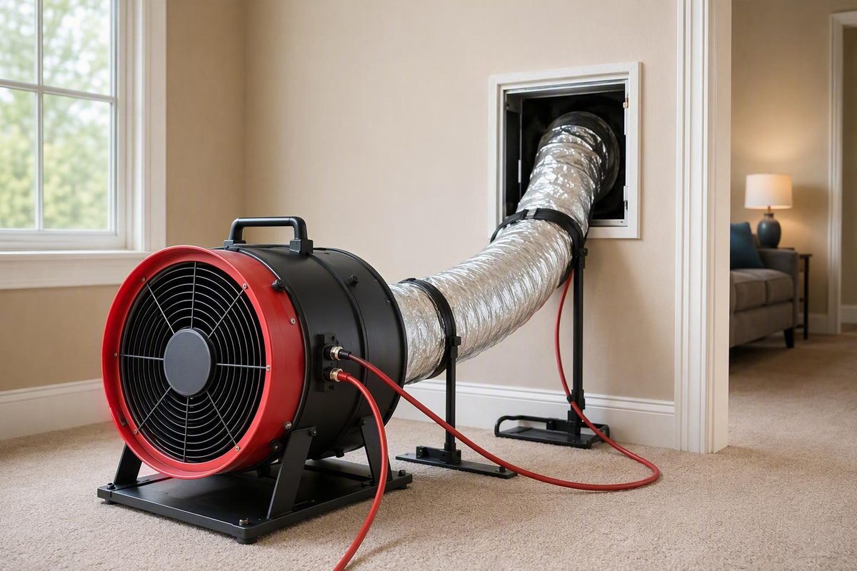
A duct blaster test gives you a measured answer to a narrow but useful question: How airtight is the tested HVAC duct system under controlled pressure?
It does not directly measure heating or cooling capacity, room-by-room airflow, equipment efficiency, refrigerant charge, or the airtightness of the house itself. Nor does it automatically reveal the location of every leak. Its main output—often reported as CFM25—becomes meaningful only when you know what portion of the system was tested, whether the result represents total leakage or leakage to outdoors, how the result was normalized, and which local requirement or program target applies.
That distinction matters when a homeowner is told that the ducts “failed.” A raw number without the test method, system boundary, comparison limit, and repair plan is not enough to support a sound decision.
What a duct blaster test measures
A duct blaster test is a controlled measurement of HVAC duct-system airtightness. It measures air passing through unintended openings in the ducts and included components. It is not a test of whether the furnace, heat pump, or air conditioner is correctly sized or capable of meeting the home’s heating and cooling load.
The basic measurement principle is straightforward:
- The tester temporarily seals intentional duct openings, including supply registers and return grilles.
- A calibrated fan is connected to the ductwork.
- A pressure-and-flow gauge measures duct pressure and airflow through the test fan.
- The fan pressurizes or depressurizes the sealed system to the prescribed test pressure.
- Once the pressure is stable, the airflow required to maintain it is recorded.
At a stable pressure, the air supplied or removed by the calibrated fan replaces the air passing through openings in the tested system. The measured fan airflow therefore represents aggregate duct leakage at that test pressure. Many residential procedures use 25 Pascals, approximately 0.1 inch of water gauge, although the tester must follow the pressure and procedure required by the applicable code, rating, certification, or project specification. The University of Illinois SEDAC overview describes this sealing-and-pressurization method and the common 25-Pascal test pressure in its duct blaster testing guidance.
When equivalent systems are tested under equivalent conditions, a lower required fan airflow generally indicates tighter ducts. Comparisons become less reliable when systems differ in size, test boundary, construction stage, test direction, or normalization method.
The test’s most important limitation is that it quantifies overall leakage but does not, by itself, identify every physical opening. A high reading may reflect one disconnected run, many poorly sealed joints, leakage through an included air-handler enclosure, or several concealed defects. Additional diagnostics are usually needed to distinguish among those possibilities.
Leak location also affects what a defect means in practice:
- A supply-side leak can release conditioned air before it reaches the intended room.
- A return-side leak can draw air from an attic, crawlspace, garage, wall cavity, or other surrounding area.
- Leakage within conditioned space contributes to a total-leakage result, but its consequences may differ from leakage into an attic or outdoors.
- A disconnected duct in an unconditioned space may have different implications from several small openings that communicate only with conditioned space.
A duct blaster result is therefore best understood as a measurement of how much aggregate leakage exists under the prescribed test conditions. It is not a complete diagnosis of every comfort, airflow, or equipment problem in the home.
What happens during the test
The exact procedure depends on the governing protocol, construction stage, and whether the scope calls for total leakage, leakage to outdoors, or both. From a homeowner’s perspective, however, a typical appointment follows a recognizable sequence.
1. The tester establishes the system boundary. Before sealing anything, the tester identifies what belongs to the system being measured. Inclusion should follow the applicable procedure rather than assumption.
Multiple HVAC systems, air handlers, or independently controlled zones may require isolation or additional testing, depending on the protocol and project scope. Homeowners should disclose these features when requesting a quote.
2. The equipment and controls are placed in the required condition. For final testing, the HVAC equipment is commonly turned off during measurement. Connected mechanical-ventilation controls may also need to be disabled or placed in the state specified by the protocol. The tester should determine the required condition of the equipment and controls before operating any test fan.
3. Intentional duct openings are temporarily sealed. Supply registers, return grilles, and relevant outdoor-air openings are covered with temporary sealing material. One connection point is left available for the test fan. These seals are not repairs; they temporarily close openings through which air is intended to move during normal operation.
Complete sealing matters. An accidentally open register or loose temporary seal can be counted as leakage and distort the result.
4. The test fan is connected. The calibrated fan is commonly attached at a central return grille or an opening in the air-handler compartment. Either arrangement may be valid when permitted by the procedure and installed correctly. The U.S. Department of Energy’s Building America Solution Center includes a government-funded demonstration of connecting a duct tester at a return register.
5. A pressure probe is installed. A small tube or probe is placed in a supply branch, often near the air handler. This allows the gauge to measure duct pressure relative to the surrounding space. Correct placement and an airtight seal around the insertion point help produce a stable, representative reading.
6. The fan and gauge are configured. The tester selects the proper fan opening, ring, measurement range, and gauge settings for the expected leakage. The objective is to operate the equipment within a suitable measurement range rather than force a result from an inappropriate configuration.
7. The ducts are brought to the target pressure. The fan either supplies air to the duct system or removes air from it. Approved procedures may permit pressurization, depressurization, or both. Depressurization is sometimes preferred because it can pull temporary sealing material toward the registers, but it is not universally required.
8. The reading is stabilized and recorded. The tester adjusts fan speed until the prescribed duct pressure is reached. After pressure and airflow stabilize, the tester records the fan airflow. Retrotec’s technical guide describes total-leakage and leakage-to-outdoors setups, including sealing intentional openings, placing a reference tube in a supply register, and testing at positive or negative 25 Pa where the governing standard permits those methods in its duct testing best-practices guide.
9. The equipment and temporary seals are removed. After measurements and any additional diagnostics are complete, the fan is disconnected. Registers, grilles, controls, access panels, and other affected components should be returned to their proper operating condition.
This walkthrough is intended to explain what a homeowner may observe, not to provide a do-it-yourself compliance procedure. Test fans alter pressure relationships, and valid work depends on equipment instructions, calibration, safety precautions, local requirements, and the governing protocol. Government-funded educational material on the procedure likewise states that users remain responsible for safety, code compliance, local regulations, and manufacturer instructions.
How to read CFM25 without mistaking it for a pass-or-fail score
CFM25 means cubic feet per minute of airflow required to maintain a 25-Pascal pressure difference across the tested duct system.
Suppose a report shows:
Total duct leakage: 120 CFM25
That means the calibrated fan had to move 120 cubic feet of air per minute to hold the tested system at 25 Pascals relative to the reference space. It does not mean the home loses exactly that amount during every minute of normal HVAC operation. It is a standardized leakage measurement taken under controlled conditions; the basic meaning of a 120 CFM25 result is illustrated in this duct-leakage testing explanation.
A raw CFM25 result does not account for home or system size. The same raw reading may represent a different relative leakage level in a small system than in a much larger one. Many requirements therefore normalize the result.
For illustration, assume that the protocol-defined conditioned floor area served by the tested system is 2,000 square feet:
120 CFM25 ÷ 2,000 square feet × 100 = 6 CFM25 per 100 square feet
The arithmetic is:
- Divide 120 CFM25 by 2,000 square feet.
- Multiply the result by 100.
- The normalized result is 6 CFM25 per 100 square feet.
This example teaches the calculation. It is not a universal allowable limit. The assumed 2,000-square-foot denominator must not automatically be treated as the whole home’s area. Depending on the protocol, the correct denominator may be the conditioned floor area served by the tested system, another defined floor area, duct surface area, or system airflow. Utah guidance provides one jurisdiction-specific example of expressing leakage per 100 square feet of conditioned floor area, but its figures must not be generalized beyond the applicable Utah rule and code version.
Different protocols may express leakage relative to:
- conditioned floor area;
- floor area served by the tested system;
- duct surface area;
- rated or measured system airflow;
- or another defined basis.
The denominator is therefore as important as the raw airflow. A result of “6” is ambiguous unless the report explains whether it means CFM25 per 100 square feet, a percentage of system airflow, leakage per square foot of duct surface, or something else.
Do not confuse CFM25 with ACH50. CFM25 commonly describes duct leakage at 25 Pascals. ACH50—air changes per hour at 50 Pascals—is commonly associated with blower-door testing of the building envelope. The boundaries, pressures, and normalization methods differ, so the metrics are not interchangeable. A HERS testing provider distinguishes these outputs in its overview of duct testing versus blower-door testing.
Instead of accepting “the ducts passed” or “the score was 120,” ask for these items in writing:
- the raw fan airflow;
- the test pressure;
- the normalized result;
- the normalization formula and denominator used;
- the system and components included in the test boundary;
- whether the result is total leakage or leakage to outdoors;
- whether the air-handler enclosure was included;
- the applicable comparison limit;
- the construction stage and compliance pathway;
- and the final pass-or-fail determination.
Those details turn an unexplained number into a result another qualified professional, code official, rater, or program administrator can review.
Total leakage versus leakage to outdoors
Two tests on the same duct system can produce different readings without either result being wrong. One may measure total duct leakage, while the other measures leakage to outdoors.
Total duct leakage includes leakage from the tested duct system into both conditioned and unconditioned locations. A supply seam leaking into a conditioned hallway chase is included, as is a seam leaking into an attic.
Leakage to outdoors is intended to isolate leakage beyond the building or thermal envelope, including leakage into spaces treated as outside under the applicable protocol. Depending on the defined building boundary, those spaces may include an attic, vented crawlspace, garage, or the exterior.
A leakage-to-outdoors test commonly uses a blower door along with the duct-testing fan. The blower door controls the pressure of the conditioned interior so that the pressure relationship between the house and the ducts is aligned or neutralized as required by the procedure. This largely excludes communication between the ducts and conditioned interior from the measured result. Under a properly performed test, the remaining fan flow represents leakage across the defined building boundary, subject to the applicable protocol and field conditions.
Consider an illustrative home whose ducts are located largely inside conditioned space. It might show 120 CFM25 of total leakage but only 20 CFM25 of leakage to outdoors. The difference would suggest that much of the measured total leakage communicates with conditioned space rather than an attic, crawlspace, garage, or exterior. Retrotec’s testing guide explains the distinct total-leakage and leakage-to-outdoors setups and the use of a blower door to match the relevant pressures.
That does not make interior leakage irrelevant. Its implications simply differ from those of a supply opening into a vented attic or a return opening into a crawlspace.
The two readings are not interchangeable. A code, energy rating, rebate, or certification program may require total leakage, leakage to outdoors, or both. Submitting a total-leakage result when the program requires leakage to outdoors does not answer the same question.
Before accepting a quote, ask:
Does this scope include total duct leakage, leakage to outdoors, or both—and is blower-door operation included?
That question can also prevent a pricing misunderstanding. A total-leakage test uses the duct-testing fan and gauge, while leakage-to-outdoors work ordinarily requires additional blower-door setup and pressure coordination.
Duct blaster, blower door, pressure pan, and other diagnostics
Several building-performance tools involve fans, gauges, pressure, or airflow, but they do not provide the same result.
| Test or diagnostic | Test target | Common metric or output | Basic setup | Primary question answered |
|---|---|---|---|---|
| Duct blaster test | HVAC duct system | CFM25 or a normalized duct-leakage rate | Registers are sealed and a calibrated fan is connected directly to the ducts | How much does the tested duct system leak at the prescribed pressure? |
| Blower door test | Building envelope | ACH50, whole-building airflow at a specified pressure, or another envelope metric | A calibrated fan is installed in an exterior doorway | How much air passes through the home’s exterior boundary under test conditions? |
| Pressure-pan diagnostic | Connection between individual registers and outside the envelope | Pressure at specific registers | A blower door operates while a pan is placed over a register | Which registers or duct paths appear strongly connected to outside? |
| Visual or smoke diagnostic | Accessible individual defects | Observed leak locations | Ducts may be placed under pressure while joints and runs are inspected | Where might air be entering or leaving? |
| Infrared or ultrasonic diagnostic | Temperature patterns or sound associated with leakage | Images, patterns, or detected signals | Specialized equipment is used under suitable conditions | Where should further inspection be concentrated? |
A duct blaster isolates and measures the HVAC duct system. A blower door measures leakage through the building envelope, including walls, ceilings, floors, windows, doors, and penetrations. Passing one test does not prove that the other system is tight.
For example:
- A home can have a tight exterior envelope and a disconnected supply duct in the attic.
- A home can have tightly sealed ducts but substantial leakage around attic hatches, plumbing penetrations, or exterior doors.
- A comfort complaint can involve both systems, such as a leaky return in a vented attic combined with envelope leakage.
The tests can therefore complement each other when construction quality, renovation, moisture, comfort, energy use, certification, or code questions involve both boundaries.
A pressure-pan test serves a different purpose. With a blower door operating, a tester places a pan over individual registers and measures pressure. Suspicious readings can help identify branches that communicate strongly with an attic, crawlspace, or exterior. The method does not produce the calibrated aggregate CFM25 result supplied by a duct-testing fan. Building-science guidance characterizes blower-door and pressure-pan testing as diagnostic rather than a substitute for a complete duct-leakage measurement in its discussion of basic duct-leakage test methods.
The same measurement-versus-localization distinction applies to other tools:
- Visual inspection can reveal disconnected runs, crushed flex duct, loose collars, and open seams.
- Smoke or test vapor may make air movement visible around accessible joints.
- Pressure diagnostics can narrow the search to particular branches or spaces.
- Infrared imaging may reveal useful temperature patterns when system operation and indoor-outdoor conditions create sufficient contrast.
- Ultrasonic equipment may detect sound associated with moving air.
No diagnostic should be presented as guaranteed to reveal every concealed or inaccessible leak. A practical sequence is often to quantify aggregate leakage first and then use one or more diagnostics to locate the defects worth repairing.
When testing is useful—and when it may be required
Duct leakage testing may be used for:
- new construction;
- rough-in verification;
- final construction testing;
- a major renovation;
- HVAC replacement where locally applicable;
- an energy rating;
- a utility rebate or incentive;
- a certification program;
- quality-control work;
- or investigation of suspected duct defects in an existing home.
A rough-in test occurs while more ducts, joints, chases, and connections remain accessible. Finding leakage at this stage can make repairs easier because drywall, ceilings, cabinets, and finishes have not yet concealed the system. The applicable procedure may also account for components that have not yet been installed.
A final test evaluates the completed system, commonly near the end of construction. Registers, grilles, air-handler components, and other included parts are then in their final configuration. Because rough-in and final test boundaries can differ, their results and limits should not be assumed to be interchangeable.
Whether testing is legally required is a local question. Requirements can vary with:
- the authority having jurisdiction;
- the adopted energy or residential code edition;
- state and local amendments;
- project type;
- whether the work is new construction, an addition, an alteration, or an equipment replacement;
- the location or percentage of ducts outside the thermal envelope;
- the rough-in or final construction stage;
- the compliance pathway;
- and the required test method.
Published regional examples show why homeowners should not rely on a threshold found in a general article. A 2025 commercial-provider summary lists different targets for North Carolina, South Carolina, and a Duke Energy new-construction program. Those figures illustrate variation but require current verification with the relevant authority or program; see the provider’s regional duct-testing score overview.
Utah-oriented guidance describes a state-amended post-construction threshold and a trigger related to the location of ducts outside the thermal envelope. Because the page does not clearly establish the currently applicable code edition or effective date, its figures should be treated as an example of state variation rather than as an automatically current or nationwide rule; see the published Utah duct leakage testing guidance.
Older IECC-based material provides another example. University of Illinois guidance describes testing under the referenced 2018 IECC when ducts are outside conditioned space and separately discusses Illinois treatment of renovations and additions. Those statements are tied to that code edition and amendment context, not a universal present-day requirement, as the university’s SEDAC guidance makes clear.
For a compliance project, verify all of the following before work begins:
- Authority: Which code official, department, rater, utility, or certification body will review the result?
- Edition: Which code or program version applies?
- Amendments: Has the state or locality modified the base provision?
- Trigger: Why is the test required for this project?
- Method: Is total leakage, leakage to outdoors, or both required?
- Stage: Must testing occur at rough-in, final, or either stage?
- Boundary: Is the air-handler enclosure included?
- Normalization: Is leakage divided by conditioned floor area, served floor area, duct area, or system airflow?
- Limit: What exact threshold applies?
- Qualifications: Must the tester hold a specific credential or authorization?
- Documentation: What form, signatures, equipment details, or filing process will be accepted?
Utility, rating, and certification targets may be stricter than minimum code or simply use a different method. Confirm the current program documents directly rather than assuming code compliance automatically qualifies a project for a rebate or certification.
For an existing home, testing can be informative when there is reason to suspect a duct defect. It should not be treated as proof that every comfort complaint originates in the ducts.
How to prepare, how long it may take, and what affects cost
Homeowners generally do not need to seal registers or configure equipment before the appointment unless the testing provider supplies specific instructions. Preparation is mainly about access and an accurate description of the scope.
Before the tester arrives:
- Provide clear access to supply registers and return grilles.
- Make the air handler, furnace, heat-pump components, filter cabinet, and relevant mechanical spaces accessible.
- Ensure the tester can reach the thermostat and required controls.
- Disclose attics, crawlspaces, garages, or locked areas containing ducts.
- Identify multiple HVAC systems, air handlers, or zones.
- Mention known disconnected, damaged, or abandoned ductwork.
- Explain whether the test is for diagnosis, code compliance, a rating, a rebate, or another formal purpose.
- Ask for provider-specific preparation and safety instructions.
The appointment includes more than the time during which the fan holds the target pressure. The tester must identify the system boundary, seal intentional openings, connect the fan and tubing, configure the equipment, stabilize the measurement, record the result, remove temporary seals, restore the system, and prepare any required documentation.
One commercial provider says most appointments take one to two hours, depending on duct-system size and layout. That is a provider estimate, not a guaranteed duration for every home or scope; see JB’s Home Energy’s published duct-testing timeframe.
Factors that may lengthen an appointment include:
- multiple systems or air handlers;
- a large number of registers;
- complex zoning;
- difficult access;
- unclear system boundaries;
- blower-door operation for leakage-to-outdoors measurement;
- diagnostic work to locate defects;
- formal compliance reporting;
- repairs during the visit;
- and retesting after repairs.
Pricing is similarly scope-dependent. One regional service provider publishes an estimated range of approximately $150 to $500, depending on property size and the number of HVAC systems. That is a local commercial example, not a national average or fixed fee, as shown on its testing information page.
EPB advertises $250 for a combined blower-door and duct-blaster service. The offer may depend on location, eligibility, current pricing, and included scope, so it should not be treated as broadly available pricing. EPB describes it on its combined air-leak testing page.
Obtain a written local quote that answers:
- How many HVAC systems are included?
- Does the scope cover total leakage, leakage to outdoors, or both?
- Is blower-door operation included?
- Does the fee include leak-location diagnostics?
- Will the provider issue a formal compliance or program report?
- Are travel charges included?
- Are sealing or repairs included?
- Is a retest included after repairs?
- Are there filing, certification, or third-party administration fees?
- What happens if the system cannot reach the target pressure?
- Will the relevant official, rater, utility, or certification program accept the report?
Also ask whether the fan and pressure gauge are calibrated as required by the applicable protocol. For formal testing, the least expensive appointment may be of little value if the method, tester qualifications, equipment records, or report will not be accepted.
What happens after a high reading or failed test
A high result should lead to a structured review, not an immediate assumption that one particular repair will solve the problem.
A practical workflow is:
- Confirm that the test was valid.
- Review the raw and normalized results.
- Identify likely defect locations.
- Select repairs appropriate to the materials and openings.
- Retest under the required conditions.
- Retain the complete report and repair documentation.
Start with test validity. Verify that the correct system was isolated, all intended registers and relevant outdoor-air openings were sealed, the pressure probe was properly placed, the prescribed target pressure was reached, and the reading stabilized. For a borderline result, it may also be appropriate to review temporary-seal integrity, fan configuration, calibration status, and any uncertainty recognized by the governing protocol.
Next, determine exactly what failed. Was the issue:
- raw CFM25;
- normalized total leakage;
- leakage to outdoors;
- a rough-in threshold;
- a final threshold;
- a code limit;
- or a stricter utility or certification target?
A high aggregate reading narrows the issue to the tested duct-system boundary, but it does not reveal every opening. Inspection or additional diagnostics may be required.
Common defect locations include:
- duct joints and seams;
- supply boots and register boxes;
- return boxes;
- supply and return plenums;
- coil-to-furnace or coil-to-plenum connections;
- air-handler and filter-cabinet connections;
- line-set and other plenum penetrations;
- takeoffs and collars;
- damaged, crushed, or torn flex duct;
- and partially or fully disconnected runs.
Repair should match the defect rather than rely on one material everywhere. Possible repair categories include:
- approved mastic for suitable accessible joints and seams;
- specialized duct-sealing tape approved for the material and application;
- caulk where appropriate around boots, boxes, and building-material interfaces;
- mechanical reconnection and proper support of loose runs;
- replacement of damaged flex duct or components;
- and professional aerosol sealing for some systems with inaccessible leakage.
Ordinary cloth-backed “duct tape” should not be treated as a universal permanent repair. Adhesive compatibility, surface preparation, temperature, pressure, accessibility, duct material, manufacturer instructions, defect type, and local requirements all affect whether a sealing method is suitable.
Aerosol sealing can be useful for some inaccessible systems, but it is a repair process—not the leakage measurement itself. The system still requires an appropriate pre-repair assessment and, where improvement or compliance must be documented, a valid post-repair test.
The final report should identify:
- the HVAC system tested;
- the tested boundary;
- the registers, grilles, and openings sealed;
- whether the air handler was included;
- the test direction;
- the target pressure;
- the raw CFM25 result;
- the normalized result and calculation basis;
- whether the result represents total leakage or leakage to outdoors;
- the governing comparison limit;
- the equipment and relevant calibration information;
- observed or suspected defects;
- repairs completed;
- and the retest result.
Before approving repairs, ask the professional:
- Where is the leakage suspected?
- What evidence points to those locations?
- How much of the leakage appears to be outside conditioned space?
- Which repair is proposed, and why is it suitable for this duct material?
- Are any defects inaccessible?
- What measurement will confirm improvement?
- Is a formal retest required?
- Who will submit or retain the final documentation?
The duct blaster result is most valuable as a decision tool, not a stand-alone verdict. You should leave the process with four facts in writing: which system and leakage method were tested, the raw and normalized CFM25 result, the locally applicable comparison requirement, and the recommended repair-and-retest path. Those facts support a sharper conversation with a qualified tester or HVAC professional than an unexplained number ever can.
Frequently asked questions about duct blaster testing
How long does a duct blaster test take?
One service provider estimates that most tests take one to two hours, depending on system size and layout. Treat that only as a planning example, not a guaranteed duration. Multiple systems, difficult access, many registers, leakage-to-outdoors testing, diagnostics, formal reporting, repairs, or retesting can extend the appointment.
Ask whether the quoted time covers only measurement or also setup, blower-door operation, leak location, reporting, and removal of all temporary seals.
How much does a professional duct blaster test cost?
There is no reliable nationwide price in the supplied published examples. One regional provider quotes approximately $150 to $500 depending on property size and system count, while EPB advertises $250 for a combined blower-door and duct-blaster service. These are local commercial examples cited in the cost discussion above, not national averages.
Request a written quote specifying the number of systems, test method, blower-door inclusion, diagnostics, report, travel, repairs, retesting, and filing or certification fees.
Can a duct blaster test show exactly where every duct leak is?
No. The primary measurement quantifies aggregate leakage within the tested duct-system boundary. It establishes how much airflow is required to maintain the prescribed pressure, but it does not automatically identify every opening.
Visual inspection, smoke, pressure-pan diagnostics, infrared imaging under suitable conditions, or ultrasonic equipment may help locate defects. Concealed or inaccessible leakage can remain difficult to pinpoint.
What is the difference between a duct blaster test and a blower door test?
A duct blaster test isolates and measures leakage from the HVAC duct system, commonly reporting CFM25. A blower door test measures leakage through the building envelope and commonly reports ACH50 or whole-building airflow at a specified pressure.
Passing one test does not prove that the other boundary is tight. The tests may be used together when a concern involves both ducts and the exterior envelope or when leakage-to-outdoors measurement requires pressure coordination with a blower door.
What is considered a passing duct blaster score?
There is no universal passing score. The allowable result can depend on jurisdiction, adopted code edition, local amendments, project type, construction stage, compliance pathway, duct location, test method, air-handler inclusion, normalization basis, and utility or certification requirements.
Ask for the exact applicable limit and its source, then compare like with like. Total leakage should be compared with a total-leakage limit, and leakage to outdoors should be compared with a leakage-to-outdoors limit. A raw CFM25 reading should not be judged against a normalized threshold until the required calculation has been completed.